NativeBIM / Demos / Footbridge on an IFC4.3 alignment
NativeBIM by NativeCAD
IFC showcase: Footbridge on an IFC4.3 alignment
A steel truss footbridge laid out along an IFC4.3 alignment, with a plan and profile sheet and a frame screening under dead and pedestrian load. It is not a real bridge.
Preliminary, not engineering. Preliminary structural screening, not engineering and not for construction. Numbers come from a simplified model and simplified loads; a licensed professional engineer designs the structure. Outputs are drafts for review by the licensed professional of record.
This model is illustrative. It is built from a script with the dimensions listed under Sources, and it does not represent an existing or as-built building.
3D model
The viewer opens footbridge-alignment.glb, the glTF that NativeBIM writes from the IFC file. The IFC file is footbridge-alignment.ifc.
What is in the model
| Item | Count or value |
|---|---|
| Slabs | 2 |
| Storeys | 1 |
Requirements
Not checked as a building: a footbridge, not a building.
Drawing set
Draft drawing set generated from the model: footbridge-alignment-drawings.pdf (PDF, 2 sheets).
- G-001 COVER SHEET AND SHEET INDEX
- A-101 DECK FLOOR PLAN
Elevations are not generated yet, so this drawing set has plans and schedules only. Sections are not generated yet, so this drawing set has plans and schedules only.
Alignment and frame screening
This showcase shows a preliminary structural screening of the model: member forces, deflections and support reactions from a linear elastic frame model under simplified loads based on ASCE 7-22. It is not engineering, not a structural design and not a check against any building code, and it is not for construction. A licensed professional engineer designs and takes responsibility for any real structure. Outputs are drafts for review by the licensed professional of record. NativeBIM is not affiliated with, endorsed by or sponsored by the companies and organizations named here. Product names and marks belong to their owners. The bridge is 30 m long in 10 panels of 3 m, laid out by station along an IfcAlignment 120 m long. The IFC4.3 geometry code evaluated the alignment written in the file and it agrees with the positions the layout used to within 1 mm at every metre of station (0 diagnostics). The frame solver then ran a linear analysis of the 114 members under dead and pedestrian live load. Under live load the midspan deflection is 16.9 mm, against a span / 360 limit of 83.3 mm; the vertical frequency estimated from the dead-load deflection is 4.99 Hz against 3 Hz in the guide specification. A guard and a round handrail run along both truss lines; the largest opening measured in the file's geometry admits a sphere of 94 mm against the 4 in (101.6 mm) limit, and the lowest top is 1070 mm over the deck against 42 in (1066.8 mm).
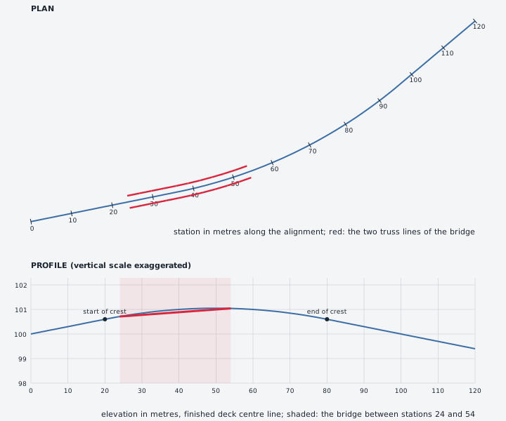
| Station (m) | x (m) | y (m) | Deck elevation (m) | Grade (percent) |
|---|---|---|---|---|
| 24 | 23.522 | 4.768 | 100.712 | 2.6 |
| 27 | 26.462 | 5.364 | 100.785 | 2.3 |
| 30 | 29.402 | 5.96 | 100.85 | 2 |
| 33 | 32.342 | 6.556 | 100.905 | 1.7 |
| 36 | 35.282 | 7.152 | 100.952 | 1.4 |
| 39 | 38.215 | 7.785 | 100.989 | 1.1 |
| 42 | 41.131 | 8.491 | 101.018 | 0.8 |
| 45 | 44.028 | 9.269 | 101.038 | 0.5 |
| 48 | 46.905 | 10.12 | 101.048 | 0.2 |
| 51 | 49.759 | 11.042 | 101.05 | -0.1 |
| 54 | 52.59 | 12.035 | 101.042 | -0.4 |
| Approach | Stations (m) | Largest running slope (percent) | Cross slope (percent) | Ramp needed |
|---|---|---|---|---|
| Start approach | 0 to 23.9 | 3 | 0 | no |
| End approach | 54.1 to 120 | 3 | 0 | no |
| Check | Value | Reference |
|---|---|---|
| Midspan deflection under pedestrian live load (mm) | 16.9 | span / 360 = 83.3 mm |
| Midspan deflection under dead load (mm) | 12.8 | used for the frequency estimate |
| Vertical frequency estimate (Hz) | 4.99 | 3 Hz or more in the guide specification |
| Largest opening through a guard, measured from the geometry in the file (mm) | 94 | a sphere of 4 in (101.6 mm) must not pass; truss members given no credit |
| Lowest top of a guard over the deck, whole length (m) | 1.07 | at least 42 in (1.067 m); handrail top 0.914 m (36 in) |
| Guard and handrail weight, both sides (kN) | 14.23 | 158.1 Pa over the deck, inside the 1500 Pa superimposed dead load already applied |
| Sum of vertical reactions, service load (kN) | 681.9 | equals the applied load and self-weight |
| Member group | Largest tension: member | kN | Largest compression: member | kN |
|---|---|---|---|---|
| Bottom chord | BC-R6 | 389.6 | BC-R10 | 446.8 |
| Top chord | TC-L10 | -1.9 | TC-R6 | 932 |
| Diagonal | D-R9 | 338.9 | D-R10 | 445 |
| Post | V-R7 | 67.3 | V-L0 | 4 |
| Node | Fx (kN) | Fy (kN) | Fz (kN) |
|---|---|---|---|
| N1 | 154.46 | 57.60 | 137.15 |
| N21 | -133.19 | 22.75 | 112.87 |
| N23 | 508.84 | 103.72 | 211.59 |
| N43 | -530.10 | -184.07 | 220.26 |
| Member | Max (mm) | Span / max |
|---|---|---|
| V-R6 | 3.95 | 607 |
| V-R7 | 3.88 | 619 |
| V-R5 | 3.58 | 670 |
| V-R8 | 3.45 | 696 |
| V-L6 | 3.07 | 783 |
The guards are not members of the frame model and add no stiffness; their weight is inside the superimposed dead load. They stand on the deck, which is not modelled as a surface, so the posts have no base fixing drawn and the guard has not been checked for the horizontal load a railing must carry.
Bearings are idealised as pins at all four support nodes with no thermal movement; the trusses are laid out on polygonal chords between the alignment points, so the curve in plan is followed to within the chord sag, not by curved members.
The viewer draws the bridge members; it has no drawing for the alignment curve, which is on the plan and profile sheet. The IFC spatial structure is an IfcBuilding with one storey because the builder does not write IfcBridge yet; the alignment sits in the IfcSite. Dimensions and loads are chosen for the sample. The largest displacement of any point is 46.35 mm, in member M58. Loads and sections are chosen for the sample.
Preliminary structural screening, not engineering and not for construction. Numbers come from a simplified model and simplified loads; a licensed professional engineer designs the structure. Outputs are drafts for review by the licensed professional of record.
Sources
Where each dimension comes from. Anything marked as chosen for the sample is an assumption, not a measurement.
- IFC4.3 alignment: IfcAlignment with IfcAlignmentHorizontal and IfcAlignmentVertical design parameters and an Axis representation of IfcCurveSegments in an IfcGradientCurve. buildingSMART IFC4.3 ADD2 (ISO 16739-1:2024), Linear positioning and Alignment concept templates.
- Alignment geometry: a 36 m line, a 60 m left arc of radius 120 m and a 24 m line in plan; 3 percent grade, a 60 m crest parabola to minus 3 percent, then a straight grade in profile. Chosen for this sample. No real road or path is represented..
- Approaches: a 2.4 m walk with a 150 mm kerb either side follows the alignment profile at each end of the bridge (3 percent up to station 20, the crest parabola, 3 percent down), a sectioned solid on the alignment, with trees and shrubs beside the kerbs. Running slope 3 percent or less everywhere, so no ramp: 1:20 is the limit of a walking surface and a steeper surface is a ramp that needs landings and handrails; the walk is level across, within the 1:48 cross slope limit. A 0.1 m movement joint separates each approach from the bridge end. 2010 ADA Standards for Accessible Design: 403.3 (running slope 1:20 and cross slope 1:48 at most), 405.2 (ramp run 1:12 at most), 405.6 (30 in rise per run), 405.7 (landings, 60 in long at the top and bottom of a run), 405.8 (handrails on a run rising over 6 in), https://www.ada.gov/law-and-regs/design-standards/2010-stds/ . The walk width, kerb, joint and planting are chosen for this sample. The approach is paving only: no terrain, drainage or cross fall is modelled. They are left out on purpose: the walk sheds water along its 3 percent running slope to the ends, and a cross fall (it would have to stay within the 1:48, 2.08 percent, of 403.3) or a graded swale beside the kerbs only means something with the ground and an outfall to take the water, and this sample has neither a terrain surface at the bridge nor a storm drainage system, so drawing a tilted walk or a ditch here would be a shape with no checked purpose..
- Truss: 10 panels of 3 m (30 m span), trusses 3.0 m apart, 2.4 m deep, Warren pattern with verticals; sections HSS8X8X1/2 chords, HSS5X5X3/8 verticals and diagonals, W12X26 floor beams. AISC shapes database dimensions, as used in tests/structural/frames.js; member sizes chosen for this sample, not designed.
- Connections: a bearing plate (3 in beyond the HSS8 chord width, 3/4 in thick) with four 3/4 in anchor rods in 1-5/16 in holes under each of the four support nodes, a 3/8 in shear tab with 3/4 in bolts in 13/16 in holes at each floor beam end, a 1/2 in gusset plate lapped on the outer face of each diagonal at each end. Assumed rules of thumb of AISC practice (Design Guide 1 for base plates, the Steel Construction Manual Part 10 for shear tabs), sized from the section dimensions above; not designed and not checked for capacity. The connections are not analytical members. Which value rests on which public AISC source, and which is not corroborated: docs/research/steel_connections.md..
- Pedestrian live load 4.3 kPa (90 psf), vertical frequency of 3 Hz or more. AASHTO LRFD Guide Specifications for the Design of Pedestrian Bridges (2009), sections 3.1 and 5.3; used here as a screening reference, not checked against the standard.
- Guard along each truss line: an IfcRailing GUARDRAIL 1.07 m high (the 42 in minimum rounded up, measured square to the deck), posts 2 in square at no more than 1.5 m and at every panel point, a top rail, a bottom rail 50 mm over the deck and 5/8 in pickets spaced so that no clear gap reaches 95 mm, under the 4 in sphere. It stands 40 mm inside the inner face of the chords on the deck and follows the deck grade panel by panel. The truss verticals and diagonals are outside it and no credit is taken for them: the guard stops the sphere by itself. The largest opening is measured from the geometry in the file (tools/showcase/guard_openings.js), not read back from the builder, and the build refuses a guard that admits a sphere of 4 in or is under 42 in anywhere. International Building Code, section 1015.3 (guard height 42 in) and 1015.4 (openings that do not admit a sphere of 4 in), as encoded in packages/core/src/authoring/builder/railings.js; recalled from public summaries and not read from the publisher (verified: false). The AASHTO pedestrian bridge guide specification the page cites for loads is the usual basis for a footbridge railing; its railing provisions were not read here, so no AASHTO railing height, opening or clause number is claimed. The guard dimensions are chosen for this sample..
- Handrail on each inner guard face: an IfcRailing HANDRAIL, a round bar of 1 1/2 in diameter, its top 36 in over the walking surface, 1 1/2 in clear of the post face, on 20 mm square brackets at every post. The approaches are not ramps, so no code requires it on this level route; it is added for the people who use the span. 2010 ADA Standards for Accessible Design, sections 505.4 (handrail height 34 to 38 in), 505.5 (1 1/2 in clearance) and 505.7.1 (round bar 1 1/4 to 2 in), recalled from public summaries and not read from the publisher (verified: false), https://www.ada.gov/law-and-regs/design-standards/2010-stds/ . Handrail dimensions chosen within them for this sample..
- Live-load deflection limit span / 360 and the frequency estimate f = 0.18 sqrt(g / d) from the dead-load deflection d. Common practice for simply supported spans; chosen for this sample.
Built 2026-11-01 with node tools/showcase/build.js footbridge-alignment. Re-running the command gives the same bytes.
Notices
NativeBIM is licensed software. It does not provide design, engineering or other professional services. Outputs are drafts for review by the licensed professional of record.
Sheets are marked NOT FOR CONSTRUCTION by default.
Areas are computed by NativeBIM, not a certified BOMA measurement.
IFC and Industry Foundation Classes are marks of buildingSMART International.
NativeBIM is not affiliated with, endorsed by or sponsored by the companies and organizations named here. Product names and marks belong to their owners.
NativeBIM is provided as is, without warranty of any kind. To the extent the law allows, FeatureBoard Labs Incorporated is not liable for indirect, incidental or consequential damages, lost profits or lost data, and its total liability is limited to the license fees paid in the 12 months before the claim. Read the license.