NativeBIM / Demos / Borgund stave church, 1180
NativeBIM by NativeCAD
IFC showcase: Borgund stave church, 1180
Borgund stave church read off its 1861 survey and solved for weight, Eurocode snow and wind: the wind it can take, and the frame in glulam, steel and concrete.
This model is illustrative. It is built from a script with the dimensions listed under Sources, and it does not represent an existing or as-built building.
3D model
The viewer opens stave-church.glb, the glTF that NativeBIM writes from the IFC file. The IFC file is stave-church.ifc.
What is in the model
| Item | Count or value |
|---|---|
| Walls | 76 |
| Doors | 3 |
| Slabs | 144 |
| Columns | 105 |
| Storeys | 1 |
Requirements
The model meets every requirement of a timber building. Each is measured on the model’s geometry by casting rays at it from sample points 0.25 m apart.
| Requirement | What it asks | Result |
|---|---|---|
| Every enclosed area has a floor | Rooms are walked on: an area walls close in at a storey level and nothing to stand on is not a room. | Met |
| The interior is closed in | Walls, doors and windows close every interior floor on all sides; a gap in the walls is a hole in the building. | Met |
| Rain from above is kept off every floor | A roof over every floor, with no gaps between its planes, at its hips and valleys, or where it meets a wall. | Met |
| Wind-driven rain does not reach the interior | Rain at 30 degrees from the vertical, from 8 directions, meets the roof or walls before an interior floor. | Met |
| Structural timber is kept out of the rain | A timber frame lasts when its members stay dry: no beam, post or brace top open to the sky. | Met |
| There is a way in | At least one door in the envelope. | Met |
Drawing set
Draft drawing set generated from the model: stave-church-drawings.pdf (PDF, 3 sheets).
- G-001 COVER SHEET AND SHEET INDEX
- A-101 CHURCH FLOOR PLAN
- A-601 DOOR SCHEDULE
Elevations are not generated yet, so this drawing set has plans and schedules only. Sections are not generated yet, so this drawing set has plans and schedules only.
Why it stands, and what it can take
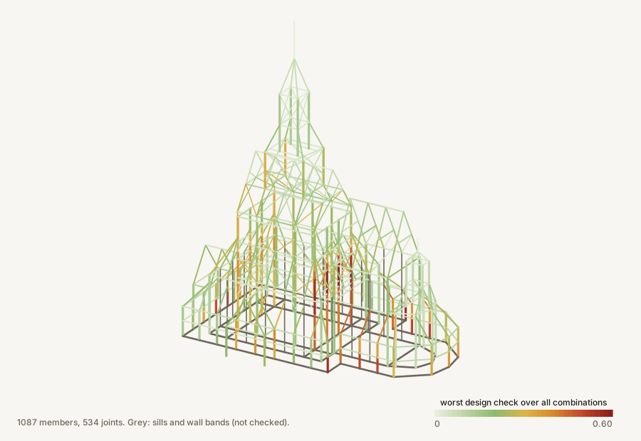
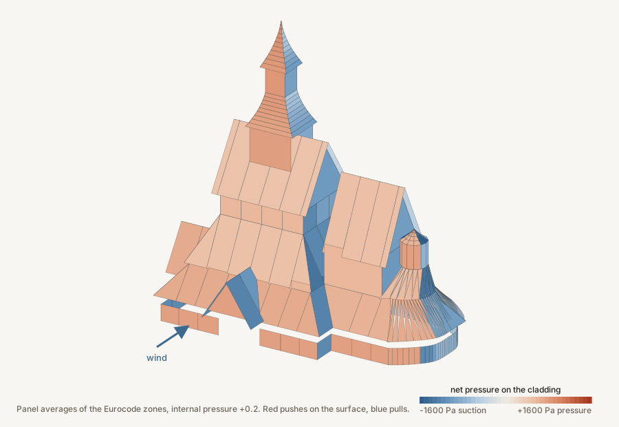
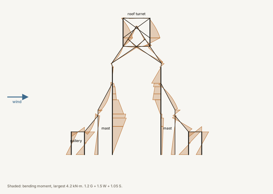
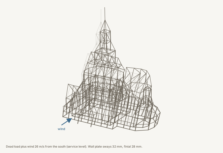
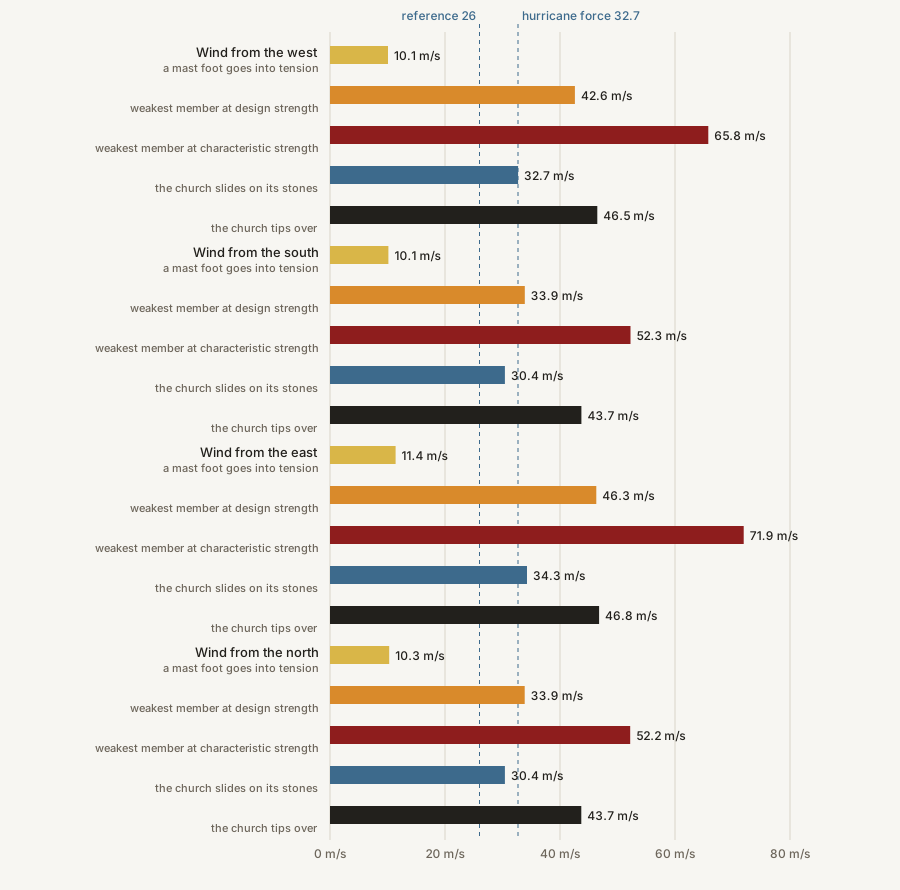
1087 frame members and 534 joints read off the 1861 survey, solved for 13 load cases and checked in 28 Eurocode combinations. The church's own weight is 47.8 t; under 1.35 times that weight the worst member check is 0.16 (1.00 is design strength). Snow does not govern: the nave roof is 56 degrees, so Eurocode's shape coefficient there is only 0.10 (0.80 on a flat roof). Wind does: the governing check is 0.59 (Mast, 1.2 G + 1.5 W (from the north, cpi 0.2)). Pushed further, the weakest member reaches its design strength (with Eurocode's safety factors) at 33.9 m/s and its characteristic strength (without them) at 52.2 m/s; the church would slide on its stones at 30.4 m/s and tip at 43.7 m/s (basic wind velocity, terrain II).
| Quantity | Model | Source | Source says |
|---|---|---|---|
| nave length, corner post centres (m) | 7.286 | 7.35 | Kringom: nave interior 7.35 m long |
| nave width, corner post centres (m) | 6.132 | 6.1 | Kringom: nave interior 6.10 m wide |
| chancel width, post centres (m) | 3.392 | 3.4 | Kringom: chancel 3.4 m square |
| chancel length, post centres (m) | 3.49 | 3.4 | Kringom: chancel 3.4 m square |
| nave floor area (m2) | 44.678 | 44.835 | Kringom: 7.35 x 6.10 m |
| mast spacing along the nave, plan (m) | 1.261 | 1.253 | Schirmer 1861, longitudinal section: posts 145 px apart at 72.6 px per alen |
| mast core width, plan (m) | 3.864 | 3.868 | Schirmer 1861, cross-section: outer mast centres 444 px apart |
| mast diameter (m) | 0.31 | 0.298 | Schirmer 1861, plan: mast circles 33 px across |
| wall plate height (m) | 6.951 | 6.969 | Schirmer 1861, cross-section (the longitudinal section reads 6.93 m) |
| nave ridge above ground (m) | 10.227 | 9.957 | Schirmer 1861, longitudinal section: 9.96 m (Kringom gives "some 11 m" floor to ridge) |
| turret width along the nave (m) | 2.495 | 2.489 | Schirmer 1861, longitudinal section: turret 288 px wide |
| number of masts | 12 | 12 | Wikipedia; Store norske leksikon (12 masts and 2 half-posts on the tang) |
| Part | Mass (t) |
|---|---|
| Frame timber (all members except the wall bands) | 22.4 |
| Roofing: boards, shingles, tar | 13.0 |
| Wall planks | 10.4 |
| Floors | 2.0 |
| Total (sum of the support reactions) | 47.8 |
| Mast at x, y (m) | G | G + S | G + W south 26 m/s | G + W north 26 m/s | G stress (MPa) |
|---|---|---|---|---|---|
| -2.5, -1.9 | 13.0 | 13.8 | -3.0 | 42.5 | 0.17 |
| -2.5, -0.6 | 8.6 | 8.8 | 3.9 | 12.8 | 0.11 |
| -2.5, 0.6 | 8.6 | 8.8 | 13.0 | 3.6 | 0.11 |
| -2.5, 1.9 | 13.1 | 13.9 | 42.7 | -3.3 | 0.17 |
| -1.2, -1.9 | 14.1 | 14.9 | 12.2 | 20.7 | 0.19 |
| -1.2, 1.9 | 14.0 | 14.8 | 20.2 | 12.5 | 0.19 |
| 1.3, -1.9 | 14.1 | 14.8 | 10.6 | 22.0 | 0.19 |
| 1.3, 1.9 | 14.0 | 14.8 | 21.5 | 10.9 | 0.19 |
| 2.5, -1.9 | 13.0 | 13.7 | -20.9 | 59.5 | 0.17 |
| 2.5, -0.6 | 9.1 | 9.4 | 2.3 | 17.3 | 0.12 |
| 2.5, 0.6 | 9.2 | 9.4 | 17.5 | 1.9 | 0.12 |
| 2.5, 1.9 | 13.0 | 13.8 | 59.4 | -21.4 | 0.17 |
| Member group | Check | Governs | Combination |
|---|---|---|---|
| Mast | 0.59 | compression and bending (6.23/6.24) | 1.2 G + 1.5 W (from the north, cpi 0.2) |
| Gallery post | 0.57 | compression and bending (6.23/6.24) | 1.2 G + 1.5 W (from the south, cpi 0.2) |
| Gallery rafter | 0.46 | compression and bending (6.23/6.24) | 1.2 G + 1.5 W (from the north, cpi 0.2) |
| St Andrew's cross | 0.44 | tension and bending (6.17/6.18) | 1.2 G + 1.5 W (from the south, cpi 0.2) |
| Roof brace | 0.36 | compression and bending (6.23/6.24) | 1.0 G + 1.5 W (from the north, cpi -0.3) |
| Turret post | 0.34 | compression and bending (6.23/6.24) | 1.2 G + 1.5 W (from the north, cpi -0.3) |
| Rafter seat | 0.32 | shear (6.13) | 1.2 G + 1.5 W (from the north, cpi 0.2) |
| Aisle hip | 0.28 | compression and bending (6.23/6.24) | 1.2 G + 1.5 W (from the north, cpi 0.2) |
| Aisle rafter | 0.28 | tension and bending (6.17/6.18) | 1.0 G + 1.5 W (from the south, cpi 0.2) |
| Nave rafter | 0.27 | compression and bending (6.23/6.24) | 1.2 G + 1.5 W (from the north, cpi 0.2) |
| Chancel rafter | 0.26 | compression and bending (6.23/6.24) | 1.2 G + 1.5 W (from the south, cpi -0.3) |
| Chancel post | 0.24 | tension and bending (6.17/6.18) | 1.0 G + 1.5 W (from the south, cpi 0.2) |
| Porch post | 0.23 | compression and bending (6.23/6.24) | 1.2 G + 1.5 W (from the north, cpi 0.2) |
| Half-post | 0.23 | tension and bending (6.17/6.18) | 1.0 G + 1.5 W (from the west, cpi 0.2) |
| Scissor arm | 0.22 | compression and bending (6.23/6.24) | 1.2 G + 1.5 W (from the north, cpi -0.3) |
| Porch rafter | 0.22 | tension and bending (6.17/6.18) | 1.2 G + 1.5 W (from the north, cpi 0.2) |
| Chancel wall plate | 0.20 | tension and bending (6.17/6.18) | 1.2 G + 1.5 W (from the east, cpi -0.3) |
| Nave wall plate | 0.20 | shear (6.13) | 1.0 G + 1.5 W (from the south, cpi 0.2) |
| Turret hip | 0.18 | compression and bending (6.23/6.24) | 1.2 G + 1.5 W (from the north, cpi -0.3) |
| Chancel collar | 0.17 | compression and bending (6.23/6.24) | 1.2 G + 1.5 W (from the south, cpi -0.3) |
| Eave beam | 0.16 | tension and bending (6.17/6.18) | 1.2 G + 1.5 W (from the west, cpi 0.2) |
| Apse rafter | 0.16 | compression and bending (6.23/6.24) | 1.2 G + 1.5 W (from the north, cpi 0.2) |
| Gallery plate | 0.15 | compression and bending (6.23/6.24) | 1.2 G + 1.5 W (from the south, cpi 0.2) |
| Belfry post | 0.15 | compression and bending (6.23/6.24) | 1.2 G + 1.5 W (from the north, cpi 0.2) |
| Nave corner post | 0.15 | tension and bending (6.17/6.18) | 1.2 G + 1.5 W (from the west, cpi 0.2) |
| Chancel tie | 0.14 | tension and bending (6.17/6.18) | 1.2 G + 1.5 W (from the east, cpi -0.3) |
| Porch plate | 0.14 | compression and bending (6.23/6.24) | 1.2 G + 1.5 W (from the north, cpi 0.2) |
| Gallery rail | 0.13 | compression and bending (6.23/6.24) | 1.2 G + 1.5 W (from the north, cpi 0.2) |
| Collar | 0.13 | compression and bending (6.23/6.24) | 1.2 G + 1.5 W (from the north, cpi 0.2) |
| Turret brace | 0.12 | compression and bending (6.23/6.24) | 1.2 G + 1.5 W (from the north, cpi 0.2) |
| Purlin | 0.11 | compression and bending (6.23/6.24) | 1.2 G + 1.5 W (from the south, cpi 0.2) |
| Core wall plate | 0.11 | tension and bending (6.17/6.18) | 1.2 G + 1.5 W (from the south, cpi 0.2) |
| Upper tang | 0.10 | tension and bending (6.17/6.18) | 1.2 G + 1.5 W (from the north, cpi 0.2) |
| Porch king post | 0.10 | tension and bending (6.17/6.18) | 1.2 G + 1.5 W (from the north, cpi 0.2) |
| Apse tower post | 0.09 | compression and bending (6.23/6.24) | 1.2 G + 1.5 W (from the south, cpi 0.2) |
| Apse post | 0.08 | tension and bending (6.17/6.18) | 1.0 G + 1.5 W (from the north, cpi 0.2) |
| Chancel ridge | 0.08 | tension and bending (6.17/6.18) | 1.0 G + 1.5 W (from the south, cpi -0.3) |
| Porch ridge | 0.08 | tension and bending (6.17/6.18) | 1.2 G + 1.5 W (from the north, cpi 0.2) |
| Apse plate | 0.08 | shear (6.13) | 1.2 G + 1.5 W (from the north, cpi 0.2) |
| Spire hip | 0.07 | shear (6.13) | 1.2 G + 1.5 W (from the north, cpi 0.2) |
| Arcade girt | 0.07 | shear (6.13) | 1.2 G + 1.5 W (from the south, cpi 0.2) |
| Belfry brace | 0.07 | tension and bending (6.17/6.18) | 1.0 G + 1.5 W (from the north, cpi 0.2) |
| Upper girt | 0.07 | tension and bending (6.17/6.18) | 1.0 G + 1.5 W (from the east, cpi -0.3) |
| Lower tang | 0.05 | tension and bending (6.17/6.18) | 1.2 G + 1.5 W (from the south, cpi 0.2) |
| Apse tie | 0.05 | compression and bending (6.23/6.24) | 1.0 G + 1.5 W (from the north, cpi 0.2) |
| Apse tower hip | 0.05 | tension and bending (6.17/6.18) | 1.0 G + 1.5 W (from the south, cpi 0.2) |
| Apse tower ring | 0.05 | shear (6.13) | 1.2 G + 1.5 W (from the south, cpi -0.3) |
| Turret plate | 0.03 | tension and bending (6.17/6.18) | 1.2 G + 1.5 W (from the north, cpi 0.2) |
| Belfry beam | 0.03 | tension and bending (6.17/6.18) | 1.2 G + 1.5 W (from the north, cpi -0.3) |
| Apse tower plate | 0.03 | shear (6.13) | 1.2 G + 1.5 W (from the south, cpi 0.2) |
| Belfry ring | 0.03 | compression and bending (6.23/6.24) | 1.2 G + 1.5 W (from the north, cpi 0.2) |
| Arcade knee | 0.03 | tension and bending (6.17/6.18) | 1.0 G + 1.5 W (from the south, cpi 0.2) |
| Ridge | 0.02 | tension and bending (6.17/6.18) | 1.0 G + 1.5 W (from the north, cpi 0.2) |
| Belfry plate | 0.01 | tension and bending (6.17/6.18) | 1.2 G + 1.5 W (from the north, cpi 0.2) |
| Upper knee | 0.01 | compression and bending (6.23/6.24) | 1.2 G + 1.5 W (from the north, cpi -0.3) |
| Finial | 0.00 | compression and bending (6.23/6.24) | 1.35 G |
| Wind | A mast or post foot goes into tension | Weakest member at design strength (Eurocode factors) | Weakest member at characteristic strength (no factors) | Slides on its stones | Tips over |
|---|---|---|---|---|---|
| from the west | 10.1 m/s | 42.6 m/s | 65.8 m/s | 32.7 m/s | 46.5 m/s |
| from the south | 10.1 m/s | 33.9 m/s | 52.3 m/s | 30.4 m/s | 43.7 m/s |
| from the east | 11.4 m/s | 46.3 m/s | 71.9 m/s | 34.3 m/s | 46.8 m/s |
| from the north | 10.3 m/s | 33.9 m/s | 52.2 m/s | 30.4 m/s | 43.7 m/s |
| Check | Hand stress (MPa) | FEA average (MPa) | Design strength (MPa) | Design check | Characteristic check | Wind at design strength (m/s) |
|---|---|---|---|---|---|---|
| Peg, double shear (30 mm hardwood) | 31.4 | not modelled | 3.12 | 10.10 | 3.98 | 14.3 |
| Sill cheeks, peg bearing across the grain | 14.8 | 13.8 | 1.73 | 8.56 | 3.37 | 14.6 |
| Tenon, peg bearing along the grain | 7.4 | 6.4 | 14.50 | 0.51 | 0.20 | 34.3 |
| Tenon, relish shear below the peg | 1.30 | 0.90 | 2.77 | 0.47 | 0.19 | 35.5 |
| Frame | Wall plate sway (mm) | Finial sway (mm) | Worst design check |
|---|---|---|---|
| As surveyed: knees, crosses and roof braces, pegged joints 100 kN.m/rad, plank walls 200 kN/m per metre | 32 | 28 | 0.59 |
| As surveyed, plank walls with no racking stiffness | 36 | 31 | 0.72 |
| As surveyed, plank walls twice as stiff (400 kN/m per metre) | 31 | 26 | 0.52 |
| Without knees, crosses and roof braces | 59 | 94 | 0.72 |
| As surveyed, loose joints 20 kN.m/rad | 78 | 61 | 1.22 |
| Without bracing, loose joints, no wall racking | 244 | 396 | 1.66 |
| As surveyed, rigid joints | 4 | 5 | 0.54 |
| Material | Frame (t) | Whole church (t) | Mast | Wall plate sway at 26 m/s (mm) | Mast stress, own weight (MPa) | Ratio to design strength | Tips over at (m/s) |
|---|---|---|---|---|---|---|---|
| Pine heartwood (as surveyed) | 22.4 | 47.8 | 310 mm solid | 32 | 0.19 | 0.019 | 43.7 |
| Glulam GL30h | 19.3 | 44.7 | 294 mm solid | 33 | 0.19 | 0.016 | 42.3 |
| Steel S355, round tubes | 22.8 | 48.2 | tube 206 mm | 27 | 3.27 | 0.009 | 43.8 |
| Concrete C30/37 (uncracked) | 64.6 | 90.0 | 236 mm solid | 30 | 0.68 | 0.040 | 59.9 |
| Face | Zone | cpe,10 | Area (m2) | Net pressure (Pa) |
|---|---|---|---|---|
| Aisle roof E | Fup | -1.20 | 2.4 | -1400 |
| Aisle roof E | H | -1.00 | 12.6 | -1200 |
| Aisle roof N | F | -0.50 | 17.4 | -700 |
| Aisle roof N | G | -0.50 | 0.8 | -700 |
| Aisle roof S | F | 0.71 | 17.5 | 512 |
| Aisle roof S | G | 0.71 | 0.8 | 512 |
| Aisle roof W | Fup | -1.20 | 2.4 | -1400 |
| Aisle roof W | H | -1.00 | 12.6 | -1200 |
| Apse roof | F | 0.75 | 5.3 | -72 |
| Apse roof | Fup | -1.20 | 1.7 | -1400 |
| Apse tower roof | F | -0.94 | 1.3 | -65 |
| Apse tower roof | Fup | -1.91 | 0.7 | -1632 |
| Apse tower wall | B | -0.80 | 2.1 | -800 |
| Apse tower wall | D | 0.80 | 2.1 | 800 |
| Apse tower wall | E | -0.51 | 2.1 | -512 |
| Belfry wall | A | -1.20 | 1.1 | -1311 |
| Belfry wall | B | -0.80 | 3.3 | -874 |
| Belfry wall | D | 0.80 | 2.2 | 874 |
| Belfry wall | E | -0.70 | 2.2 | -765 |
| Chancel east wall | A | -1.20 | 0.9 | -1400 |
| Chancel east wall | B | -0.80 | 6.2 | -1000 |
| Chancel gable | A | -1.20 | 0.2 | -1400 |
| Chancel gable | B | -0.80 | 5.6 | -1000 |
| Chancel roof N | I | -0.20 | 3.4 | -400 |
| Chancel roof N | J | -0.30 | 13.0 | -500 |
| Chancel roof S | F | 0.72 | 13.0 | 523 |
| Chancel roof S | H | 0.72 | 3.4 | 523 |
| Chancel wall | D | 0.80 | 7.9 | 600 |
| Chancel wall | E | -0.51 | 7.9 | -712 |
| Clerestory | A | -1.20 | 1.8 | -1400 |
| Clerestory | B | -0.80 | 7.9 | -1000 |
| Clerestory | D | 0.80 | 6.3 | 600 |
| Clerestory | E | -0.51 | 6.3 | -712 |
| Gallery parapet | A | -1.20 | 4.8 | -1200 |
| Gallery parapet | B | -0.80 | 9.2 | -800 |
| Gallery parapet | D | 0.80 | 11.4 | 800 |
| Gallery parapet | E | -0.51 | 11.4 | -512 |
| Gallery roof | F | 0.70 | 21.0 | 157 |
| Gallery roof | Fup | -1.40 | 3.8 | -1400 |
| Gallery roof | G | 0.70 | 9.0 | 559 |
| Gallery roof | H | -1.00 | 40.3 | -568 |
| Gallery roof | I | -0.83 | 3.1 | -833 |
| Nave gable E | A | -1.20 | 0.6 | -1400 |
| Nave gable E | B | -0.80 | 6.5 | -1000 |
| Nave gable W | A | -1.20 | 0.6 | -1400 |
| Nave gable W | B | -0.80 | 6.5 | -1000 |
| Nave roof N | I | -0.15 | 7.6 | -348 |
| Nave roof N | J | -0.22 | 15.3 | -423 |
| Nave roof S | F | 0.70 | 15.3 | 500 |
| Nave roof S | H | 0.67 | 7.6 | 474 |
| Nave wall band | A | -1.20 | 1.5 | -1400 |
| Nave wall band | B | -0.80 | 2.5 | -1000 |
| Nave wall band | D | 0.80 | 3.3 | 600 |
| Nave wall band | E | -0.51 | 3.3 | -712 |
| Porch N gable | E | -0.51 | 2.4 | -512 |
| Porch N roof | Fup | -1.26 | 5.6 | -1261 |
| Porch N roof | H | -1.00 | 4.7 | -1000 |
| Porch S gable | D | 0.80 | 2.4 | 800 |
| Porch S roof | Fup | -1.26 | 8.2 | -1261 |
| Porch S roof | H | -1.00 | 2.2 | -1000 |
| Porch W gable | A | -1.20 | 0.0 | -1200 |
| Porch W gable | B | -0.80 | 2.5 | -800 |
| Porch W roof | F | 0.70 | 10.6 | 86 |
| Spire | F | 0.72 | 0.3 | 842 |
| Spire | Flow | -1.20 | 0.1 | -1402 |
| Spire | G | 0.72 | 0.3 | 828 |
| Spire | H | 0.73 | 3.7 | -272 |
| Spire | I | -0.66 | 2.3 | -683 |
| Turret roof | F | 0.72 | 0.6 | 769 |
| Turret roof | Flow | -1.22 | 0.2 | -1283 |
| Turret roof | Fup | -1.23 | 0.1 | -1277 |
| Turret roof | G | 0.72 | 2.2 | -51 |
| Turret roof | H | 0.75 | 7.1 | -284 |
| Turret roof | I | -0.74 | 4.1 | -648 |
| Turret wall | A | -1.20 | 1.3 | -1220 |
| Turret wall | B | -0.80 | 4.9 | -813 |
| Turret wall | D | 0.80 | 5.6 | 813 |
| Turret wall | E | -0.67 | 5.6 | -678 |
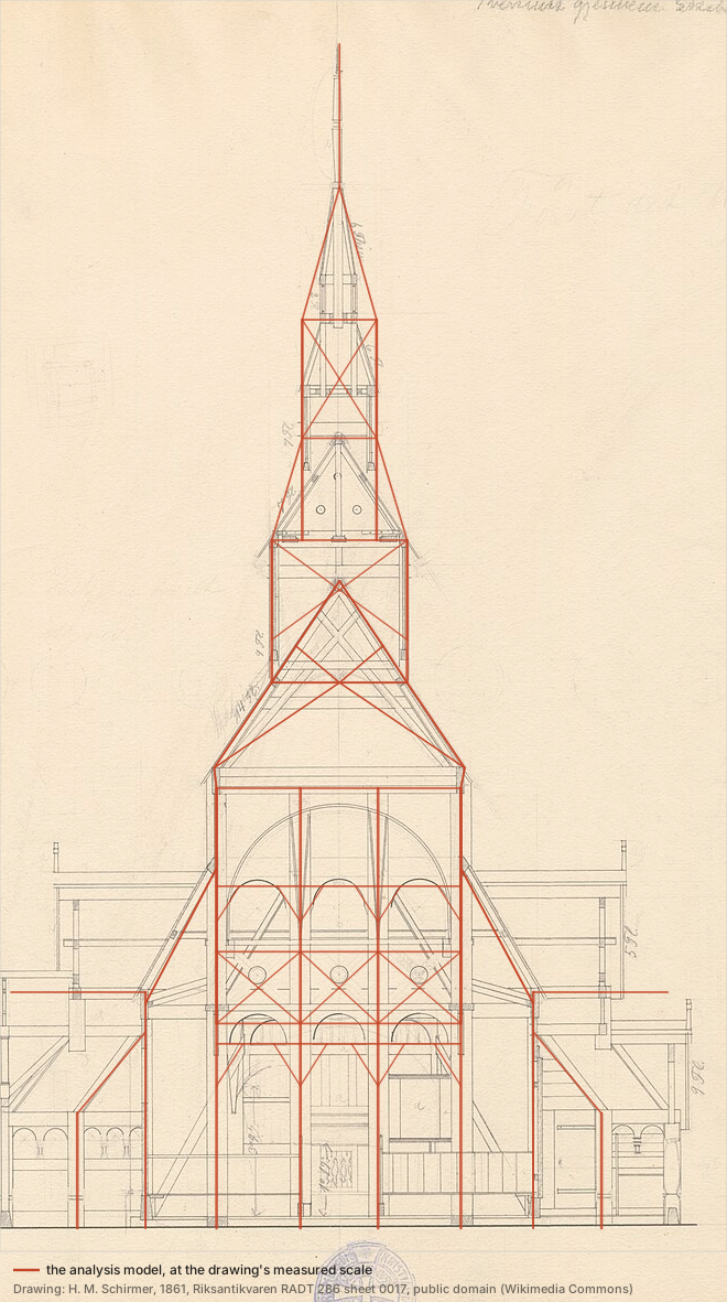
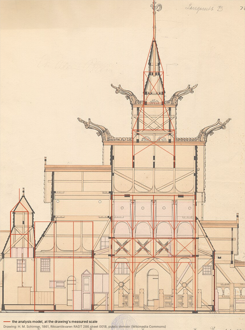
Geometry: the mast core, nave walls, gallery, chancel, apse and turret are measured off Schirmer's 1861 survey (plan, cross-section and longitudinal section); the section sizes of the rectangular timbers, the plank thickness and the roofing weight are chosen. The gallery's solid parapet (0.94 m) and open arcade, and the side and west porches, are taken from the same sheets; as in the photographs, each porch roof runs back over the gallery roof to the nave wall, meeting it in valleys. The roofs and walls the viewer shows are the load panels themselves, so the analysis is solved on the same shapes: every roof runs on into a 0.45 m eave (chosen; the eave's load goes to the rafter feet, its small lever arm over the plate is not modelled), the turret roof, the spire and the apse tower's cap flare out at the eaves (bell-cast, with round-tipped scale shingles), the apse is round in plan with a cone roof up to a round drum on its tower, and the gallery runs round the east end on a curve through the surveyed posts. These follow the photographs; the survey gives the frame, not the curves. Drawn but not loaded: the boards and shingles' thickness outside the frame, the dragon heads, crosses, bargeboards and porch lattice (traced off Schirmer's detail sheets), and the gallery arcade, portals with their oak doors and iron hinges, belfry arcade, porch arches and the hoods at the gable feet (read off the photographs with chosen sizes).
Loads: own weight (pine 500 kg/m3), roofing 450 Pa, planks 392 Pa, floors 350 Pa; ground snow 3 kPa with Eurocode's shape coefficient on each roof plane, balanced and unbalanced, and a held-snow case (0.8 on every roof); wind 26 m/s in four directions with internal pressure +0.2 and -0.3. These are chosen values, not Borgund's code values.
Load path: each roof or wall panel is cut into 15 cm cells; each cell's force goes to the two members its boards span between (rafters, plates, girts or posts) by the lever rule, and lands on the frame as member point loads (23435 of them).
Joints: masts are continuous; every pegged beam end is a rotational spring of 100 kN.m/rad; knees, crosses and roof braces are pin-ended; the sills sit on the stones with no anchorage, so lifting, sliding and tipping are limits of the building, not of a fixing. The stave walls are bands of 80 mm planks with their out-of-plane stiffness, plus an in-plane racking stiffness of 200 kN/m per metre of wall (pin-ended equivalent diagonals in each bay, analysis only): a chosen value, about one hundredth of what the planks would give if they could not slip in their grooves. The bracing table shows the results with none and with twice as much.
Checks: EN 1995-1-1 compression or tension with bending (buckling over the length between joints), and shear, at 13 points along every member, with C24 strengths, kmod for the shortest load in the combination and gamma_M 1.3. Not checked: the joints themselves (except the mast foot, below), lateral-torsional buckling, bearing across the grain at the sills.
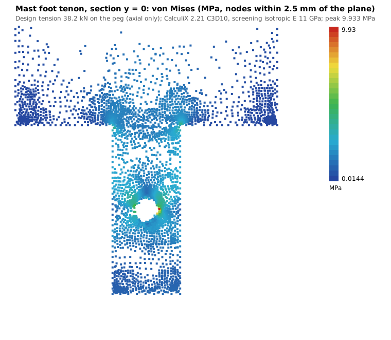
Mast foot joint (fea/): the worst design uplift at a mast foot is 44.4 kN (Mast 7, 1.0 G + 1.5 W from the north, cpi -0.3). One pegged tenon is checked for it by hand and with two solid CalculiX models, the tenon and the sill, solved once for 38.2 kN and committed as recorded output (provenance in fea/RECORDED.json); the solids are linear elastic and the hand checks are force over an area, so the table scales every value to the uplift the frame gives now. The joint sizes are chosen as typical for the period (310 mm mast, 80 x 200 mm tenon 200 mm deep, one 30 mm peg), not measured, and the solids are isotropic. The tenon is lightly used (its FEA averages agree with the hand values). The peg in double shear is not: 10.10 at design and 3.98 at characteristic level. The foot starts to lift at 12.4 m/s (design level) and one peg reaches its design strength at 14.3 m/s; the sill cheeks bearing on the peg across their grain follow at 14.6 m/s. Both checks are conservative (a peg breaks across its own grain, several times stronger than the shear strength used here, and Eurocode 5 dowel embedment strength is several times fc,90,k), but the reading stands: a pegged foot is not a hold-down. The frame model ties every mast foot to the ground; at Borgund the masts stand on the groundsill frame, which can only hold them down with its own weight and the walls'.
The wind limits are unfactored for lifting, sliding and tipping (the wind at which the church's own weight is used up), and at design level for the members (1.0 G or 1.2 G with 1.5 W). Equilibrium residual of the dead load solve: 8.5e-14.
A screening study of an illustrative model, not an assessment of the real building and not engineering advice. The 1861 survey drawings shown are in the public domain (credits in the figure captions).
Sources
Where each dimension comes from. Anything marked as chosen for the sample is an assumption, not a measurement.
- Dragon head (sheet 0114), porch cross, bargeboard width and porch gable lattice (north elevation, sheet 0010): the carved boards in showcases/stave-church/ornaments.js. H. M. Schirmer, measured drawings of Borgund stave church, 1861, Riksantikvaren RADT 286 sheets 0114 and 0010, public domain.
- Porch roofs running back over the gallery roof, pointed shingles, colours, gallery arcade, portals, belfry arcade and gable hood (read off, not reproduced). Photographs of Borgund stave church on Wikimedia Commons by Bjørn Erik Pedersen (2016, 2023, CC BY-SA 4.0), mendhak (2018, CC BY-SA 2.0) and Ximonic (2013, CC BY-SA 3.0).
- Plan, cross-section and longitudinal section; every coordinate of the frame (pixel readings in showcases/stave-church/geometry.js). H. M. Schirmer, measured drawings of Borgund stave church, 1861, Riksantikvaren RADT 286 sheets 0127, 0017 and 0018, public domain.
- Nave 7.35 x 6.10 m, chancel 3.4 m square, apse 1.88 x 2.98 m, nave about 11 m floor to ridge. Kringom, Borgund stave church (after Henden Aaraas, Vengen and Gjerde, 1999).
- Timber felled 1180/81 (dendrochronology); 12 masts with two half-posts; tang, crosses and scissor roof. Store norske leksikon, Borgund stavkirke; Wikipedia, Borgund Stave Church.
- Over 1200 wooden nails in the main structure; knee brackets of root wood. Fortidsminneforeningen, Digitale Borgund (2021).
- Wind: peak velocity pressure, terrain II, Tables 7.1, 7.3a/b, 7.4a/b, Figures 7.4 to 7.8; snow shape coefficient Table 5.2. EN 1991-1-4:2005+A1:2010 and EN 1991-1-3:2003 recommended values (not the Norwegian national annex).
- Combinations 6.10b and Table A1.2(A); timber C24, kmod, gamma_M 1.3, member checks 6.1 to 6.3. EN 1990:2002, EN 338:2016, EN 1995-1-1:2004 recommended values.
- Reference wind 26 m/s, ground snow 3.0 kPa, roofing 0.45 kPa, planks 80 mm, floor 0.35 kPa, joint stiffness 100 kN.m/rad, friction 0.5, rectangular section sizes. Chosen for this study, not Borgund's code values and not measured.
Built 2026-10-31 with node tools/showcase/build.js stave-church. Re-running the command gives the same bytes.
Notices
NativeBIM is licensed software. It does not provide design, engineering or other professional services. Outputs are drafts for review by the licensed professional of record.
Sheets are marked NOT FOR CONSTRUCTION by default.
Areas are computed by NativeBIM, not a certified BOMA measurement.
IFC and Industry Foundation Classes are marks of buildingSMART International.
NativeBIM is not affiliated with, endorsed by or sponsored by the companies and organizations named here. Product names and marks belong to their owners.
NativeBIM is provided as is, without warranty of any kind. To the extent the law allows, FeatureBoard Labs Incorporated is not liable for indirect, incidental or consequential damages, lost profits or lost data, and its total liability is limited to the license fees paid in the 12 months before the claim. Read the license.