The Boom sprint core, reconstructed from one afternoon of public frames
On 7 September 2026 Blake Scholl posted a short clip — "Things are really coming together" — from Boom Supersonic's engine hangar, and a few stills went round with it: a polished nozzle ring on an assembly table with its vane segments laid out around it, technicians torquing a variable-stator case with the stations numbered in marker, a compressor rotor hanging from a yellow gantry, and the whole core stack standing on a yellow build stand in front of a Schenck balancing machine tagged BOOM 01. NativeCAD rebuilt the hardware in those frames as real, fastened, clash-checked parts, and this page also reads everything else in the room.
Independent reconstruction by NativeCAD from public sources. Not affiliated with or endorsed by Boom Supersonic; all names are trademarks of their owners. Original photos: Blake Scholl on X. See our reference image policy.
Vertical build
Every part on this page bolts into one stack — base plate, adapter ring, front cone, the front-frame ring, the mid case, the eight HPT nozzle-support rings, and the high-pressure turbine rotor coming down on its crane bridle. Every joint on the way up is a real fastener — bolts, rivets, pins — and every touching pair of parts was checked: zero clashes. Press play, or step through it a flange, a sheet, a bolt set at a time; click any part to zoom to it, and switch to X-ray or a cut-away to see the nozzle and the rotor inside the stack.
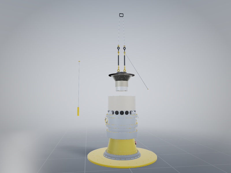
Drag inside the scene to orbit, scroll to zoom, click a body to zoom to it. The camera refits when you switch parts.
What is in the frame
The public captions say only sprint core. Reading the hardware in the original post, in the order the gas would meet it, this is what the frames show — and the evidence for each reading is the shape of the part, not a drawing.
- The forward case, olive-drab. The tall chem-film/anodised aluminium case at the top
of the stack (the greenish-gold one with BUFFER AIR lettering, blue tape and a dozen
instrumentation tags stencilled
P5xx-99xx) is the front of the high-pressure compressor: machined bosses for bleed and buffer air, pressure taps wired out along cable-tie lines. Aluminium, because it is cold enough there. - The variable-stator case. Below it, stainless: two rows of trunnion bosses, each with a flat lever and a yellow cad-plated nut, the stations numbered 1…50 in marker along the top row. That is the VSV mechanism — every lever will pin to a unison ring so one actuator rotates a whole row of stator vanes. The close-up of the split-line flange shows the bolt torque-sequence numbers (4, 2, 6, 10, 14, 18, 22 …) written on a masking strip: a star pattern, working out from the middle.
- The HPC rotor. Hanging from the gantry hook by a lifting fixture, eight bladed stages on one drum, stage-1 blades tallest, the flow path visibly contracting aft. Blade counts rise stage by stage as the blades shorten. The photo shows blisk-like bladed discs on a bolted spool; the model seats every stage's cambered, platformed blades by their dovetails in the disc rims, closing that same continuous ring.
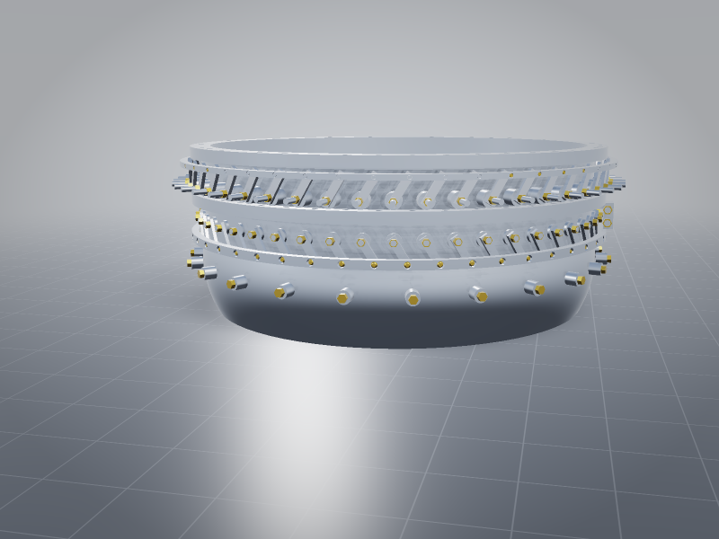
- The HPT nozzle ring and its vane segments. The polished ring on the assembly table has twin bolted flanges and twelve conical radial bosses — the pattern of a fuel-injector or instrumentation-rake ring at the combustor exit — and its bore is full of thermocouple leads. The segments laid around it (each an airfoil between two platforms, some with green thermocouple wire still attached, part numbers lasered on the platforms) are the stage-1 turbine nozzle guide vanes about to go in. Boom has said the test article's HPT blades, vanes, turbine-centre-frame vanes and blade outer air seals are printed in Haynes 282; these segments have the matte, as-built look of that.
- The build stand. The yellow round base is stencilled
PN BS03801345 REV AandWEIGHT = 1,902 LBS, with 90°/180° index marks; the pedestal ring isBS03801351and the adapter ring above the twelve postsBS03801356 REV A. TheBSprefix is Boom's own part-number series — and this stencil is the one number on this page that is not a guess, which is why the stand's mass check is shown separately below.
20 reconstructions
Each card is one reconstruction, shown as a live 3D model with its STEP file to download, the dimensions it was built to and the result of its clash check.
Also in this family
The boom-ref series started a week earlier from the rotor-balancing clip; these were built under their own tickets and are not regenerated here.
The room around the parts
The background is as legible as the foreground. Each item below is what the frame supports; where a rating or a model is inferred rather than read, it says so.
Schenck horizontal balancing machine, HM40BU, asset "BOOM 01"
The teal-and-grey enclosure with two windows behind the assembly table is a Schenck RoTec
horizontal hard-bearing balancer in its protective enclosure; the control cabinet at the left of the
frame carries the SCHENCK wordmark and reads HM40BU. In Schenck's HM series the
BU suffix is the underslung belt drive (universal, smooth-running); the U-only
variants are end-drive for high power.
| Rotor weight, max | 3,000 kg (HM40; the HM4 sibling is 1,500 kg) |
| Rotor diameter, max | 1,600 mm |
| Bearing distance, max | 1,750 mm |
| Journal diameter | 15–240 mm |
| Drive | 7.5 kW, min. balancing speed 120 rpm |
| Minimum achievable residual unbalance | 8 g·mm |
| Bed | ≈ 3,150 × 2,700 × 2,000 mm |
A 4 ft, 8-stage HPC rotor sits comfortably inside that envelope. The balancing-rig reference part in this family is an HM-class skeleton of exactly this machine type.
Yellow steel A-frame gantry crane, Wallace tri-adjustable class
The safety-yellow gantry with tapered upper legs, a red capacity plate and 8-inch swivel casters with foot brakes is the form of a Wallace Cranes tri-adjustable steel gantry (adjustable height, span and tread; U.S.-built; 1–5 t in the steel Lite/Medium ranges). The plate is not legible in any frame, so no rating is quoted as fact: the loads seen under it — the rotor and single modules like the 1,902 lb stand — fit a 2–3 t unit, and the whole 14,000 lb core would not be lifted on it.
Hanging off the near leg is a white tag reading MAGNET – FOD RISK: a magnetic tool
flagged for foreign-object-debris control, which is the surest sign in the frame that this is an
aero-engine build room and not a prototype shop.
The SPRINT CORE banner
A printed fabric banner of the core's cross-section hangs on the back wall: a bellmouth inlet on the left (the rig breathes room air — there is no fan or LP compressor on a core test), a long multi-stage HPC, the annular combustor, the HPT and the exhaust to the right. It is a general- arrangement drawing at banner resolution — no dimension on it is readable, and none was used.
Shop furniture
A clear polycarbonate shield on wheels between the balancer bay and the desks; yellow-and-black chain barrier posts marking the machine's exclusion zone; a pedestal fan aimed at the enclosure; a wire hardware rack with blue and red bins under a SUPPLIES STATION sign; a pallet jack; crates and a JBL speaker on the near one; wash bottles of isopropyl on the table; purple nitrile gloves on everyone touching hardware; lime masking tape on every flange face awaiting a part.
Symphony and the sprint core, by the public numbers
| Engine | Symphony — two-spool, medium-bypass turbofan, no afterburner; 40,000 lbf (178 kN) takeoff thrust; single-stage 72 in (1.8 m) fan; air-cooled multi-stage turbine; Mach 1.7 supercruise; 100 % SAF-capable. Four per Overture. |
| Sprint core | High-pressure compressor + combustor + high-pressure turbine as a stand-alone test article: about 12 ft long, 4 ft in diameter, 14,000 lb. |
| Additive parts | 193 functional parts printed for the test article in Haynes 282 (a γ′-strengthened nickel superalloy) on an EOS M 400-4 four-laser machine, depowdered on a Solukon SFM-AT800-S, then HIP, heat treatment, CT and X-ray: HPT blades, HPT vanes, TCF vanes, blade outer air seals. For test, not flight. |
| Combustor | Single-nozzle rig tests weekly since November 2025 at Georgia Tech's Ben T. Zinn Combustion Lab; the engine carries a full ring of nozzles. |
| Test site | Colorado Air and Space Port, Watkins CO (the former Reaction Engines site), a $3–5 M fit-out; first core run expected Q3 2026 — "a few weeks" as of 30 August. |
| Partners | Florida Turbine Technologies (Kratos) — design; Colibrium Additive (GE Aerospace) — AM consulting; StandardAero — production assembly (San Antonio). |
- Blake Scholl, 7 Sep 2026 — the clip these frames come from
- Boom FlyBy — Turning powder into power (the 193 Haynes 282 parts)
- Boom FlyBy — A small flame with big implications (12 ft × 4 ft, Georgia Tech rig)
- Luxurylaunches, 30 Aug 2026 — 14,000 lb, "a few weeks away"
- Wikipedia — Boom Symphony (thrust, fan, architecture, partners)
- Schenck RoTec — HM horizontal balancing machines · HM40BU / HM4BU data as republished by a reseller
- Wallace Cranes — portable gantry cranes
More demos
All demos →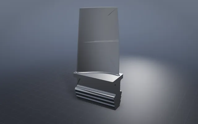
A turbine blade, boxed in by four solvers
Castability, rim load, tip clearance and aero each draw a wall, and the picked blade clears every one.
8 solved designs to compare IMTS casing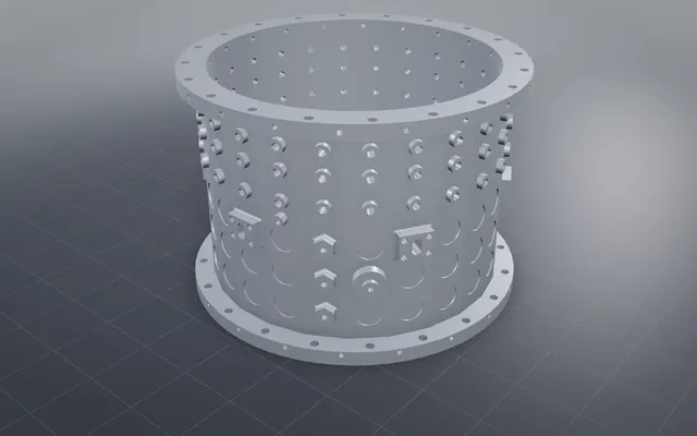
A jet-engine casing, from a reference photo to a solved model
A machined casing rebuilt from one photo, every island fillet blended and the machining check passed.
42/42 root fillets blended VSV mechanism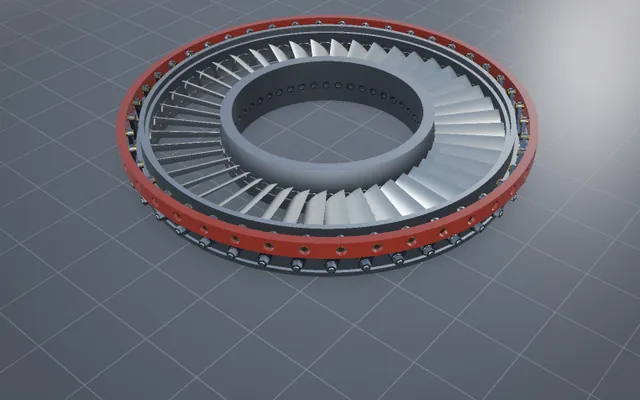
Variable stator vanes, driven from the actuator to every vane
Every compressor vane swings in step through levers, rings and one torque shaft, with every fit measured.
652 parts · 3 vane rows Rear differential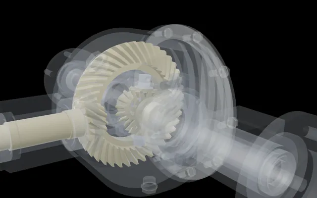
One wheel held, the other turns twice as fast
A complete rear differential with every bolt modelled, driven only by its mates, its feature tree open.
59 parts · 123 matesBuild your own part with NativeCAD
Free for education and makers with a registered key · $200 per seat per year · Kernel SDK for products.