NativeCAD · Design for manufacturing

DFM knowledge packs — the design database behind text-to-CAD

A knowledge pack is a sector's design facts — seat heights, key pitches, standoff patterns, material tables, fastener clearances, test standards and worked recipes — in a shape an agent can search before it calls a single modeling tool. Packs come in three sizes (core for the numbers a bracket-grade model needs by default, standard for a real design session, full for reference), one file per sector so a session pays only for what it uses. They are loaded by the cad_design_knowledge MCP tool.

29packs
1572entries
87recipes
410.8 KB / 1.1 MB / 1.2 MBbytes (core / standard / full)

This page fetches data/dfm/dist/index.json at load time and repaints from it when reachable; the numbers above render first from a build-time snapshot so the page works offline or from a static mirror.

The packs

SectorTitleEntries (core/standard/full)Bytes (core/standard/full)RecipesAliasesDownload
aerospaceAerospace -- drone frames, motor mounts, payload rails and airframe hardware18 / 52 / 5214.1 KB / 39.1 KB / 39.1 KB3—corestandardfull
appliancesAppliances — panels, knobs, switches, hinges, lamps and kitchen/bath hardware19 / 57 / 7015.0 KB / 42.8 KB / 51.0 KB3—corestandardfull
automotiveAutomotive — brackets, sheet-metal body/structure, die-cast and trim, EV and underhood20 / 53 / 5314.3 KB / 44.4 KB / 44.4 KB3—corestandardfull
bikesBikes -- frames, drivetrain, cockpit, e-bikes, scooters and helmets20 / 51 / 5115.5 KB / 37.4 KB / 37.4 KB3—corestandardfull
consumerConsumer products — housings, enclosures, handheld devices18 / 50 / 5413.0 KB / 38.2 KB / 40.7 KB3—corestandardfull
desk-everydayDesk & everyday objects — stands, holders, hooks, boxes, organisers18 / 51 / 5412.4 KB / 33.7 KB / 35.9 KB3—corestandardfull
desktop-robotsDesktop & companion robots -- small humanoids, robot pets, rovers, AI devices18 / 43 / 4315.2 KB / 35.7 KB / 35.6 KB3—corestandardfull
electronicsElectronics — PCBs, enclosures, connectors, heat sinks, DIN-rail devices19 / 57 / 5914.4 KB / 42.2 KB / 43.3 KB3—corestandardfull
fdm-x1cBambu Lab X1 Carbon - design rules for parts that print first time17 / 39 / 4214.6 KB / 38.5 KB / 42.0 KB2—corestandardfull
furnitureFurniture — desks, chairs, tables, shelving, cabinets22 / 57 / 6713.7 KB / 35.0 KB / 40.0 KB3—corestandardfull
furniture-constructionFurniture construction & joinery — how a chair is actually built20 / 76 / 8614.0 KB / 60.6 KB / 65.5 KB12—corestandardfull
garden-outdoorGarden & outdoor — planters, birdhouses, hose fittings, mailboxes, stakes17 / 45 / 4514.2 KB / 35.4 KB / 35.4 KB3—corestandardfull
hardwareHardware — fasteners, threads, holes, inserts, pins16 / 40 / 5215.0 KB / 34.0 KB / 42.7 KB0—corestandardfull
jewellery-wearablesJewellery & wearables — rings, pendants, bracelets, watches, glasses18 / 50 / 5113.9 KB / 36.8 KB / 37.5 KB3—corestandardfull
kitchen-tablewareKitchen & tableware — mugs, bowls, bottles, cutlery, cutters, boards22 / 44 / 4414.8 KB / 32.1 KB / 32.1 KB3—corestandardfull
maker-enclosuresMaker enclosures — Raspberry Pi, Arduino, ESP32 cases and project boxes15 / 39 / 4012.7 KB / 32.6 KB / 33.1 KB3—corestandardfull
marineMarine — hulls, deck hardware, through-hulls, corrosion and outboard mounting19 / 50 / 5215.2 KB / 37.9 KB / 39.1 KB3—corestandardfull
materialsMaterials — metals, plastics, wood and composites for any process26 / 46 / 5414.3 KB / 31.4 KB / 36.0 KB0—corestandardfull
medicalMedical devices — biocompatibility, sterilization, cleanability, labware15 / 50 / 5613.5 KB / 40.0 KB / 44.1 KB3—corestandardfull
mounts-bracketsMounts & brackets — VESA, tripod, GoPro, wall, shelf, extrusion17 / 47 / 5412.9 KB / 37.1 KB / 41.2 KB4—corestandardfull
peripheralsPeripherals — keyboards, mice, controllers, headsets16 / 47 / 5213.8 KB / 39.3 KB / 42.5 KB3—corestandardfull
pipingPiping -- pipe, tube, fittings, flanges, manifolds, O-rings and ducting16 / 59 / 5912.9 KB / 46.1 KB / 46.1 KB3—corestandardfull
power-transmissionPower transmission — gears, sprockets, racks, cams, cranks, belts18 / 46 / 4615.3 KB / 46.8 KB / 46.8 KB3—corestandardfull
roboticsRobotics -- shafts, bearings, gears, belts, motors and linkages18 / 59 / 5914.4 KB / 44.3 KB / 44.3 KB3—corestandardfull
sheet-metalSheet metal — brackets, enclosures, racks and press-brake formed parts16 / 54 / 5813.5 KB / 40.0 KB / 42.5 KB3—corestandardfull
standards-testingStandards & testing — tolerances, fits, surface finish, environmental and compliance tests16 / 44 / 4513.2 KB / 32.1 KB / 32.5 KB0—corestandardfull
toolingTooling - fixture plates, jigs, workholding, gauges20 / 61 / 6914.6 KB / 41.9 KB / 46.4 KB3—corestandardfull
toys-gamesToys & games — dice, chess, bricks, spinners, puzzles, miniatures19 / 57 / 5714.6 KB / 41.5 KB / 41.5 KB3—corestandardfull
turbomachineryTurbomachinery — gas-turbine rotor blades, discs and investment-cast aerofoils16 / 45 / 4815.9 KB / 62.7 KB / 69.3 KB3—corestandardfull
All sectors, one file: all.core.json all.standard.json all.full.json

Browse

Click a pack to expand its core entries — the numbers cad_design_knowledge loads by default.


Aerospace -- drone frames, motor mounts, payload rails and airframe hardware 18 core entries
dimension

CF plate thickness for drone frame arms and center plates

Drone frame arms and center plates are cut from carbon-fiber/epoxy plate at 2, 3 or 4 mm -- 2mm for small whoops and non-structural covers, 3mm for 5-7in racing arms, 4mm for 10in+ or load-bearing center plates.

one of 2, 3, 4

Common FPV frame-manufacturer plate-thickness convention scaled to arm/plate span and prop torque

Sources: oscar-liang-frame-guide

dimension

CF tube diameter and wall for round drone arms

Round carbon-fiber arm tubes run 16, 20, 25 or 30mm OD at a 1mm wall -- larger diameter for bigger motors and props, the 1mm wall standard across sizes because that is what pultruded CF tube is stocked at.

odMm: 16, wallMm: 1 (+3 more rows)

Standard pultruded CF tube stock sizes used by FPV frame manufacturers

Sources: oscar-liang-frame-guide

dimension

Motor-to-motor diagonal by propeller size

Frame diagonal (motor shaft to motor shaft) scales with prop size: about 210mm for 5in props, 300mm for 7in, 450mm for 10in -- undersize it and adjacent props overlap or strike the frame.

propIn: 5, diagonalMm: 210 (+2 more rows)

Common FPV frame-sizing convention relating motor-to-motor diagonal to propeller diameter

Sources: oscar-liang-frame-guide

rule

Propeller tip clearance: prop-to-prop and prop-to-frame

Keep tip-to-tip clearance between adjacent propellers, and between any prop tip and the frame or canopy, at least 10-15% of the propeller diameter -- e.g. >=13-19mm clear on a 5in (127mm) prop -- or vibration and yaw authority both suffer.

10–15 %

Common FPV/multirotor prop-clearance design rule expressed as a percentage of prop diameter

Sources: oscar-liang-frame-guide

dimension

Motor bolt-circle (square-pattern) sizes by stator frame

Brushless motor 4-hole mount squares scale with stator size: 22xx square12mm M2 or square16mm M3, 28xx square19mm M3, 4108/5008 square25mm M3/M4, 6215+ square30mm M4 -- read the actual motor's back plate, the 4-digit code only bounds the stator, not the hole spacing.

frame: 22xx, squareMm: 12, bolt: M2 (+4 more rows)

Common outrunner BLDC motor back-plate bolt-square conventions across drone motor vendors

Sources: tmotor-mn-series, iflight-xing-motor

dimension

Motor shaft and prop-adapter thread

Multirotor motor shafts are dia5mm with an M5 threaded tip for a prop nut or collet-style prop adapter -- the near-universal size across 22xx through 4108-class motors.

field: shaftDia, value: 5 (+1 more rows)

T-Motor/iFlight mechanical drawings for 22xx-4108 class multirotor motors

Sources: tmotor-mn-series, iflight-xing-motor

fastener

M3 standoff lengths for a stacked FC/ESC deck

Nylon or aluminium M3 standoffs at 20, 25, 30 or 35mm space a stacked flight-controller/ESC/VTX deck off the frame -- pick the length by stack height plus a few mm of clearance for wiring underneath.

one of 20, 25, 30, 35

Common FPV stack-mounting standoff length series sold across frame kits

Sources: oscar-liang-frame-guide

dimension

Flight controller 30.5x30.5mm mounting pattern

The dominant FPV/mini-quad flight-controller mount is four M3 holes on a 30.5x30.5mm square -- match this before any other FC footprint, it is the de facto standard across brands.

field: pattern, value: 30.5x30.5 (+1 more rows)

Industry-standard FPV flight-controller mounting square used across ArduPilot/PX4-compatible boards

Sources: ardupilot-pixhawk-standard

dimension

LiPo battery bay envelope by common pack size

Size the battery bay to the pack: 4S 1500mAh about 35x34x75mm, 6S 1300mAh about 36x34x70mm, 3S 2200mAh about 105x35x25mm, 6S 5000mAh about 155x48x40mm (W x H x L) -- add 1-2mm clearance per side for the strap and heat-shrink wrap.

pack: 4S 1500mAh, wMm: 35, hMm: 34, lMm: 75 (+3 more rows)

Common LiPo pack envelope dimensions across major hobby battery vendors (Tattu/CNHL-class packs)

Sources: oscar-liang-frame-guide

fastener

1/4-20 UNC camera mounting thread

Action/FPV cameras and gimbal quick-release plates use a 1/4-20 UNC thread (0.25in major dia, 20 threads per inch) -- the universal tripod/camera mount standard; an M6 tapped hole is only a rough geometric substitute, do not call it equivalent on a drawing.

1/4-20 UNC in

ASME B1.1 Unified inch screw thread series; 1/4-20 is the de facto universal camera-mount thread

Sources: asme-b1-1-unc

rule

Minimum thrust-to-weight ratio for stable hover

Target thrust-to-weight >=2:1 at full throttle for stable, controllable hover with headroom for wind and maneuvering -- a 1:1 airframe can only just hover with zero control authority left over.

≥ 2 ratio

Common multirotor propulsion-sizing rule of thumb for hover stability and control margin

Sources: oscar-liang-frame-guide

tolerance

CG offset from the prop-plane centroid

Keep the airframe's center of gravity within +-5mm of the geometric centroid of the motor/prop plane -- beyond that the flight controller trims out a persistent tilt at the cost of thrust margin and battery life.

≤ 5 mm

Common multirotor CG-balance tolerance relative to the prop-plane centroid

Sources: oscar-liang-frame-guide

rule

Lightening-hole and web sizing on a pocketed structural plate

On a pocketed aluminium or CF plate, leave webs at least 1.5x plate thickness wide, round pocket corners to >=3mm radius, and keep any lightening-hole diameter <=60% of the flange width -- undersize these and the pocket becomes the fatigue-crack origin.

param: minWebMultiplier, value: 1.5 (+2 more rows)

Sandia/NASA isogrid and aerospace lightweighting design-handbook pocket/web sizing conventions

Sources: sandia-isogrid-handbook

material

7075-T6 aluminium for high-strength brackets and mounts

7075-T6 (yield about 503 MPa, density 2.81 g/cm3) is the go-to aerospace aluminium for highly-loaded brackets, arms and motor mounts where strength-to-weight matters most; it welds poorly compared with 6061, so use it for machined/CNC parts, not fabricated weldments.

property: yield, value: 503, unit: MPa (+1 more rows)

MatWeb 7075-T6 aluminium property data, the standard high-strength aerospace bracket alloy

Sources: matweb-materials

material

6061-T6 aluminium for general airframe fittings

6061-T6 (yield about 276 MPa, density 2.70 g/cm3) trades some strength for weldability and machinability versus 7075-T6 -- the default for landing gear, standoffs and fittings that do not need 7075's peak strength.

property: yield, value: 276, unit: MPa (+1 more rows)

MatWeb 6061-T6 aluminium property data, the general-purpose aerospace/airframe fitting alloy

Sources: matweb-materials

material

Carbon-fiber/epoxy plate for frame arms and plates

3K/12K woven CF/epoxy plate (density about 1.55 g/cm3, in-plane tensile about 550 MPa) is the default drone-frame material: stiff, light and machinable by CNC router or laser, but it splinters at a drilled edge without a pilot hole and chamfer.

property: density, value: 1.55, unit: g/cm3 (+1 more rows)

MatWeb woven CF/epoxy laminate property data, typical drone-frame plate/tube layup

Sources: matweb-materials

tolerance

Frame hole-position tolerance by process

Hold general frame/arm hole positions to +-0.05mm on a CNC-machined or laser-cut CF/aluminium part, versus +-0.2mm on a 3D-printed part -- the same CNC-vs-FDM capability gap seen across every sector in this knowledge base.

process: CNC, toleranceMm: 0.05 (+1 more rows)

Common CNC vs FDM positional-tolerance capability gap applied to drone frame hole patterns

Sources: oscar-liang-frame-guide

test

Handheld-drone drop test

Drop a handheld-launch drone from 500-1000mm onto a hard level surface in landing orientation and on one corner; the frame, arms and prop guards should show no crack propagation past a single layer of skin -- 1000mm is a common small-UAS reference height.

500–1000 mm

Common small-UAS handheld drop-test height, aligned to typical launch/landing mishap heights

Sources: faa-14cfr107

Appliances — panels, knobs, switches, hinges, lamps and kitchen/bath hardware 19 core entries
dimension

Pre-painted steel appliance panel gauge

Pre-painted (coil-coated) steel appliance panels run 0.6-0.8 mm thick; thinner oil-cans across a large flat span, thicker adds weight and press tonnage without a stiffness benefit at this size.

0.6–0.8 mm

Common coil-coated steel gauge range for washing-machine/dishwasher/oven outer panels balancing oil-canning resistance against formability and cost

Sources: astm-en-sheet-steel

dimension

304 stainless appliance panel gauge

A 304 stainless show panel (fridge door, range hood, oven fascia) runs 1.0 mm thick, thicker than painted steel because stainless has no paint film to hide print-through of the ribs behind it.

1 mm

Standard stainless show-panel gauge that resists oil-canning and rib print-through on an unpainted, reflective surface

Sources: astm-en-sheet-steel

dimension

Plastic appliance fascia panel thickness

A moulded ABS/PP appliance fascia (control panel, door liner) runs 2.5-3 mm nominal wall, thicker than a consumer-housing wall because it usually carries printed graphics and a control cluster's mounting bosses.

2.5–3 mm

Appliance fascia panels run thicker than typical consumer-housing walls to stay flat under printed-graphic lamination and boss loads

Sources: appliance-fascia-molding-guide

dimension

Control-knob D-shaft bore standards

A control knob bores for a 6 mm D-shaft with a 4.5 mm flat-to-flat dimension, or a 6.35 mm (1/4 in) round/D shaft on larger potentiometers; match the bore to the pot's published shaft spec, not the knob vendor's default.

param: d-shaft-6mm, diameter: 6, flat: 4.5 (+1 more rows)

Common potentiometer/encoder D-shaft and 1/4in round-shaft dimensions used across appliance control knobs

Sources: bourns-knobs

dimension

Control-knob diameter and grip height

Size an appliance control knob 30-45 mm in outer diameter with a 15-25 mm grip height above the panel, enough for a wet or gloved hand to find and turn it without brushing the neighbouring control.

param: diameter, min: 30, max: 45 (+1 more rows)

Common appliance control-knob envelope balancing hand ergonomics, panel spacing and mould cost

Sources: bourns-knobs

dimension

Rocker switch panel cutout

The two common rocker-switch panel cutouts are 19.2 x 13 mm (mini rocker) and 30 x 22 mm (standard rocker); cut to the switch datasheet's own cutout tolerance, not a rounded number, since a rocker's bezel rarely has gasket compliance to hide a mismatch.

param: mini-rocker, width: 19.2, height: 13 (+1 more rows)

Standard rocker-switch bezel cutout families used across household appliance panels

Sources: iec-60335-1

dimension

Push-button panel hole diameters

Panel-mount push buttons come in three common round cutouts, ⌀12, ⌀16 and ⌀19/22 mm; the ⌀22 mm size is also the standard emergency-stop and industrial pilot-light bezel, reused on heavier appliances.

one of 12, 16, 19, 22

Standard panel-mount push-button bezel diameter family shared across household and light-industrial control panels

Sources: iec-60335-1

dimension

Concealed Euro hinge cup bore

A concealed (Euro-style) cabinet hinge bores a ⌀35 mm cup 12 mm deep into the door's back face; boring past 13 mm risks breaking through a typical 16-19 mm cabinet-door panel.

param: cup-diameter, value: 35 (+1 more rows)

Industry-standard concealed hinge cup bore size fitting the common 16-19 mm cabinet-door panel thickness

Sources: en-1935

dimension

Metric cable gland panel hole diameters

Drill a metric cable gland's panel hole to M12 -> 12.5 mm, M16 -> 16.5 mm, M20 -> 20.5 mm; the 0.5 mm over the nominal thread size is the gland's own clearance for the locknut to draw the gasket down without cross-threading in sheet metal.

param: m12, hole: 12.5 (+2 more rows)

Manufacturer panel-hole recommendation for metric cable glands threading directly into sheet metal or a moulded boss

Sources: lapp-skintop

dimension

IEC C14 inlet panel cutout

An IEC 60320 C14 appliance inlet (the standard 3-pin mains socket on the back of most appliances) needs a 27.5 x 19.8 mm rectangular panel cutout plus the moulded flange's own screw bosses either side.

param: width, value: 27.5 (+1 more rows)

EN/IEC 60320-1 C14 appliance-coupler panel cutout dimension

Sources: en-60320

dimension

E26/E27 Edison screw lamp holder envelope

An E27 (Europe) or E26 (North America) Edison-screw lamp holder has a ⌀26-27 mm threaded shell and a body/ring diameter around 40 mm; the two caps are close enough to interchange mechanically but not electrically rated the same in every market.

param: thread-diameter, min: 26, max: 27 (+1 more rows)

IEC 60061 Edison-screw cap/holder gauge for the E26/E27 family

Sources: iec-60061-lampcaps

dimension

GU10 and MR16 lamp base envelope

A GU10 twist-lock base spaces its two pins 10 mm apart on centre; the MR16 reflector lamp it commonly pairs with (12 V, bi-pin base) is ⌀50 mm across the reflector face — size the fixture's reflector pocket to that, not the base.

param: gu10-pin-spacing, value: 10 (+1 more rows)

IEC 60061 GU10 twist-lock pin gauge and the standard MR16 reflector lamp outer diameter

Sources: iec-60061-lampcaps

dimension

Zhaga Book 3 LED Light Engine Surface (LES) diameters

A Zhaga Book 3 LED module's light-emitting surface (LES) comes in four standard round diameters, 9, 13, 19 and 23 mm; pick the fixture's optic and heatsink pocket to whichever LES size the chosen module family publishes.

one of 9, 13, 19, 23

Zhaga Book 3 interoperability specification for LED light engines with separate control gear

Sources: zhaga-book3

rule

Natural-convection LED heatsink thermal budget

Budget 2-4 W of LED heat per 100 cm2 of natural-convection aluminium heatsink surface to hold the LED junction at or below 85 C; below that ratio the fixture needs forced air or a bigger fin area, not a better LED.

2–4 W

Typical natural-convection aluminium heatsink dissipation density used to keep an LED's junction near its rated maximum

Sources: cree-xlamp

rule

Touchable-surface temperature limit (IEC 60335-1)

A user-touchable appliance surface must not exceed 60 C on metal or 70 C on plastic under normal operation, measured with a 12 mm-diameter articulated finger probe reaching every opening the probe can enter.

param: metal, value: 60 (+1 more rows)

IEC 60335-1 accessible-surface temperature-rise limits and the standard finger-probe geometry used to define "touchable"

Sources: iec-60335-1

dimension

Kitchen cabinet module coordinating sizes

European kitchen cabinetry coordinates on a 600 mm module width, 720 mm carcass height, 560 mm carcass depth, with a finished worktop height of 870-920 mm above the floor once plinth and countertop are added.

param: module-width, value: 600 (+3 more rows)

EN 1116 coordinating dimensions for kitchen furniture and built-in appliances

Sources: en-1116

dimension

Built-in appliance niche openings

Size a built-in oven niche 595 x 595 mm and a built-in dishwasher niche 600 x 850 mm (width x height) so the appliance's own trim frame can seal to the cabinetry without shimming.

param: oven-niche, width: 595, height: 595 (+1 more rows)

EN 1116 standard built-in appliance niche openings used across European kitchen cabinetry

Sources: en-1116

dimension

Door handle backset and spindle size

A residential door lever/knob sets on a 60 or 70 mm backset (centre of the spindle to the door edge) with an 8 mm square spindle; mixing backsets between the lock and the handle is the most common field-fit failure on a hardware order.

one of 60, 70

Common residential door-hardware backset family and the standard 8 mm square follower spindle

Sources: bhma-a156

dimension

Adjustable appliance feet thread and load

Adjustable appliance feet thread on M8 or M10 studs and carry 80-150 kg each depending on foot diameter and material, enough for four feet to level and support a washing machine or a full oven under dynamic spin/door loads.

80–150 kg

Common adjustable-foot thread sizes and per-foot static/dynamic load rating for major household appliances

Sources: iec-60335-1

Automotive — brackets, sheet-metal body/structure, die-cast and trim, EV and underhood 20 core entries
fastener

Bracket and mount bolt class: M6/M8/M10, 8.8 vs 10.9

Chassis and bracket bolts run M6, M8 and M10 mostly in property class 8.8; 10.9 is used where the joint is fatigue- or shear-critical (engine mounts, suspension brackets) — never mix a 10.9 bolt with an 8.8 nut.

one of M6 class 8.8, M8 class 8.8, M10 class 8.8, M8 class 10.9, M10 class 10.9

ISO 898-1 property classes; 10.9 reserved for fatigue-critical joints per common OEM fastener standards

Sources: sae-j2340

fastener

Weld nut sizes for body-in-white attachment

Square and hex weld nuts for body brackets run M5–M10, projection-welded to 0.7–2.0 mm panel; pilot hole is the nut's tapped size plus 0.5–1.0 mm to seat the weld projections without arc blow.

one of M5, M6, M8, M10

Common OEM weld-nut standards (e.g. GM/Ford weld-fastener specs) size the pilot to the projection ring, not the thread

Sources: gmw3172

fastener

Clip and christmas-tree fastener hole sizes

Christmas-tree (arrowhead) push clips take a ⌀6.3 mm or ⌀8 mm panel hole in 0.7–3 mm sheet or trim; ⌀6.3 mm is the common 2-leg clip, ⌀8 mm the heavier 4-leg / high-retention clip.

one of 6.3 mm hole, 8 mm hole

Trim-clip vendor catalogs (ITW, Nifco, Bollhoff) standardise on these two panel-hole sizes across 0.7–3 mm stock

Sources: gmw3172

fastener

Push-pin (nylon dowel) fastener hole sizes

Nylon push-pin fasteners take ⌀6.5, ⌀7 or ⌀8 mm mating panel holes depending on pin family; the pin's flared shank interferes 0.2–0.5 mm past the hole to lock, so undersizing 0.1 mm below spec loses retention.

one of 6.5 mm hole, 7 mm hole, 8 mm hole

Common trim push-pin catalog hole callouts (e.g. Ford/GM interior trim fastener specs)

Sources: gmw3172

fastener

U-nut / J-nut spring clip panel thickness range

U-nuts and J-nuts (spring steel push-on nuts) clamp onto 0.6–2.5 mm flange panels; select by flange thickness first, then by the screw's major diameter (commonly M5–M6 for trim, M6–M8 for structural clips).

0.6–2.5 mm

Spring-clip nut catalogs size the leg spread to a flange-thickness range, independent of thread size

Sources: gmw3172

dimension

Outer body panel gauge (skin panels)

Exterior skin panels (doors, fenders, hood, roof) run 0.7–0.8 mm cold-rolled or HSLA steel, or 0.8–1.0 mm for aluminium skins, to hold class-A surface with minimum mass.

0.7–0.8 mm

Dent-resistance vs. mass trade-off standardised across OEM body-panel gauge tables

Sources: sae-j2340, astm-a1011

dimension

Bracket sheet-metal gauge

Formed steel brackets (mounting brackets, reinforcements, small load-carrying stampings) run 1.0–2.0 mm, chosen by the fastener class and the bracket's span rather than by panel-class rules.

1–2 mm

Typical OEM bracket-gauge tables for M6–M10 fastener classes on cantilevered brackets

Sources: astm-a1011

dimension

Structural sheet-metal gauge (rails, crossmembers, load paths)

Structural stampings that carry crash or chassis load (rails, crossmembers, pillar reinforcements) run 2.0–3.0 mm HSLA/DP steel, thicker where a hot-stamped boron grade is not used.

2–3 mm

Load-path stampings need section modulus that 2.0 mm and below cannot give without a hot-stamped grade

Sources: astm-a1011, sae-j2340

rule

Hole-to-edge and hole-to-bend distance on automotive stampings

Keep a hole centre >= 2x its diameter from a cut edge and >= 2.5x the material thickness plus the bend radius from a bend line, or the flange tears or the hole distorts during forming.

General sheet-metal tearing/distortion limits near a bend, tighter than the generic edge-distance rule because of springback

Sources: astm-a1011

process

Die-cast aluminium (A380) nominal wall thickness

A380 high-pressure die-cast walls run 2–4 mm nominal; below 2 mm the die fills unreliably, above 4 mm the section develops shrink porosity and extends cycle time.

2–4 mm

NADCA process-capability wall-thickness guidance for A380 HPDC

Sources: nadca-403

rule

Die-cast draft angle

A380 die-cast exterior walls need 1-2 deg of draft per side to release from the die without galling; textured or deep-cavity walls want the higher end.

1–2 deg

NADCA draft-angle recommendation for aluminium HPDC

Sources: nadca-403

rule

Die-cast rib thickness vs. wall

Ribs on an A380 casting should stay at or below 60% of the adjacent wall thickness to avoid sink marks on the show surface opposite the rib.

typical 60 %

Cooling-rate mismatch at a rib-to-wall junction thicker than 60% pulls the opposite face in as it solidifies

Sources: nadca-403

dimension

Injection-moulded trim wall thickness (PP/TPO)

Interior and exterior trim panels in PP or TPO mould at 2.5–3.5 mm nominal wall; thinner sections risk short shots across a large flow length, thicker sections add sink and cycle time.

2.5–3.5 mm

PP/TPO flow-length-to-wall ratio at typical trim-panel flow lengths (300-800 mm)

Sources: sae-j1455

rule

Trim panel draft angle, plus grain allowance

PP/TPO trim walls need >= 1 deg draft per side to eject cleanly; add roughly +1 deg of draft per 0.025 mm of texture/grain depth so a grained panel with 0.075 mm texture wants about 4 deg.

≥ 1 deg

Standard injection-mould grain-draft allowance (mold-tech style guidance): +1 deg per 0.025 mm texture depth

Sources: sae-j1455

dimension

Underhood ambient temperature by mounting zone

Underhood component ambient runs 105 C for engine-bay-general locations, up to 125 C near the exhaust manifold shield, and up to 150 C for parts clamped directly to the engine block or turbo heat shield.

105–150 C

ISO 16750-4 climatic-load temperature classes by mounting location

Sources: iso-16750-4

rule

Bracket first natural frequency > 200 Hz

A vehicle bracket should keep its first bending mode above 200 Hz so it does not resonate with the engine's firing-order excitation band or road-induced random vibration below that frequency.

≥ 200 Hz

Keeps the bracket's fundamental clear of typical 4-cylinder firing-order and chassis random-vibration content (10-200 Hz band)

Sources: iso-16750-3

tolerance

Body-in-white tolerance under an RPS / 3-2-1 datum scheme

Body-in-white sheet-metal assemblies hold approximately +/-0.5 mm at the reference point system (RPS) locators; feature-to-feature tolerance on a single stamping is typically +/-0.3-0.5 mm.

typical 0.5 mm

Standard OEM RPS tolerance stack-up target for BIW sub-assembly build

Sources: gmw3172

tolerance

Machined automotive component tolerance

Machined automotive features (bearing bores, mount faces, bolt patterns) hold +/-0.1 to +/-0.2 mm general tolerance, tightening to +/-0.02-0.05 mm on bearing fits and sealing faces.

0.1–0.2 mm

Typical OEM machining general-tolerance class for cast/machined automotive components

Sources: nadca-403

rule

EV battery enclosure sealing target: IP67

An EV battery pack enclosure seals to IP67 (dust-tight, 1 m submersion for 30 min) at minimum, using a compressed EPDM or silicone gasket at the lid-to-tray joint with continuous bolt-and-groove compression.

IP67 text

ISO 20653 / IEC 60529 IP67 is the common minimum EV pack sealing target across OEM specs

Sources: iso-20653, iec-60529

rule

Mechanical shock pulse: 20 g automotive component

Automotive brackets and enclosures should survive a 20 g, 6-11 ms half-sine mechanical shock pulse without fracture or fastener loosening, applied in each of 3 axes.

typical 20 g

ISO 16750-3 mechanical shock test severity for chassis- and body-mounted components

Sources: iso-16750-3

Bikes -- frames, drivetrain, cockpit, e-bikes, scooters and helmets 20 core entries
dimension

Steel frame tube diameters and butted wall gauge

Steel (chromoly) frame tubes run 25.4, 28.6 or 31.8 mm OD, double-butted to a 0.8-0.9 mm centre wall (thicker at the welded ends) -- the standard top/down/seat-tube sizing for a lugged or TIG-welded steel frame.

one of 25.4, 28.6, 31.8

Common steel-frame tubeset sizing (Reynolds/Columbus-style) referenced across Park Tool and Sheldon Brown frame-building pages

Sources: park-tool-standards, sheldon-brown-glossary

dimension

Aluminium frame tube diameters and wall gauge

Aluminium frame tubes oversize to 34.9 or 38.1 mm OD with a 1.2-1.6 mm wall -- larger diameter, thinner wall, trading steel's stiffness-per-weight for aluminium's lower modulus at similar mass.

one of 34.9, 38.1

Common aluminium-frame tubeset OD/wall convention (6061/7005 hydroformed and butted tubing)

Sources: park-tool-standards

dimension

BSA threaded bottom bracket shell

BSA (English) threaded BB shells are 68 mm (road/gravel) or 73 mm (MTB) wide, threaded 1.37 in x 24 TPI -- right (drive) side left-hand thread, left side right-hand thread, so the cups tighten rather than unscrew under pedalling.

one of 68, 73

BSA (British Standard Cycle) threaded bottom bracket shell width and thread convention

Sources: park-tool-standards, shimano-dealer-manual

dimension

PF30 press-fit bottom bracket shell

PF30 press-fit shells bore to 46 mm ID over a 68 mm shell width, pressing the bearing cups directly into the frame shell rather than threading them -- wider bearing spacing than BSA for a stiffer, lower-friction bottom bracket.

field: boreID, value: 46 (+1 more rows)

PF30 press-fit bottom bracket standard bore and shell width

Sources: park-tool-standards

dimension

T47 threaded bottom bracket shell

T47 threads a 47 mm ID cup directly into a PF30-width (68 or 73 mm) shell -- combining PF30's wide bearing stance with a threaded interface that avoids press-fit creak.

47 mm

T47 threaded bottom bracket standard cup ID and shell width options

Sources: park-tool-standards

dimension

BB86/BB92 press-fit bottom bracket shell

BB86 (road, 86.5 mm shell) and BB92 (MTB, 89.5-92 mm shell) press-fit bearings directly into a 41 mm ID shell bore -- narrower bore than PF30 because the bearings press straight into carbon-moulded cups rather than into an aluminium insert.

41 mm

Shimano BB86/BB92 press-fit bottom bracket shell bore specification

Sources: shimano-dealer-manual, park-tool-standards

dimension

Fork steerer diameters: 1-1/8 in straight and 1.5 in tapered lower

A standard 1-1/8 in steerer is 28.6 mm; a tapered fork's larger lower bearing race seats a 1.5 in (39.8 mm) steerer section, giving the head tube more stiffness where steering loads are highest.

field: steerer1-1/8in, value: 28.6 (+1 more rows)

Standard 1-1/8 in threadless steerer OD and the tapered (1-1/8-to-1.5 in) fork's lower steerer-race diameter

Sources: park-tool-standards, sheldon-brown-glossary

dimension

Integrated headset cup/head-tube ID by standard (ZS44/ZS56/IS42/IS52/EC34)

Head tube or cup ID by integrated headset standard: ZS44 44 mm, ZS56 56 mm, IS42 42 mm, IS52 52 mm, EC34 34 mm -- get the wrong ID and the bearing cup either falls through the head tube or never seats.

standard: ZS44, id_mm: 44 (+4 more rows)

Common zero-stack (ZS) / integrated (IS) / external-cup (EC) headset head-tube-ID naming convention

Sources: park-tool-standards, sheldon-brown-glossary

dimension

Quick-release dropout over-locknut distance and axle diameter

Quick-release hubs space to 100 mm over-locknut distance (OLD) front, 135 mm rear, on a 9 or 10 mm skewer/axle diameter -- the legacy hub-spacing pair that thru-axle standards replaced.

field: frontOLD, value: 100 (+2 more rows)

Standard quick-release front/rear over-locknut spacing and skewer diameter

Sources: sheldon-brown-glossary, park-tool-standards

dimension

Thru-axle diameter x OLD combinations and thread pitches

Thru-axles run 12x100 (front road), 12x142 (rear road/gravel), 12x148 Boost (rear MTB) and 15x110 Boost (front MTB), threaded M12x1.0, M12x1.5 or M12x1.75 depending on brand -- diameter x OLD must match the frame/fork exactly, thread pitch only has to match the axle's own nut.

one of 12x100, 12x142, 12x148, 15x110

Common thru-axle diameter/OLD combinations and the thread-pitch variation across axle brands

Sources: sram-standards, park-tool-standards

fastener

Derailleur hanger bolt hole

A rear derailleur hanger mounts on a dia10 mm hole tapped M10x1, threaded into the dropout's replaceable hanger tab -- the hanger is meant to bend or snap before the derailleur or frame does in a chain/spoke strike.

M10x1 mm

Standard replaceable derailleur hanger mounting bolt and hole diameter

Sources: park-tool-standards, sheldon-brown-glossary

dimension

Disc-brake caliper mount standards (IS, post mount, flat mount)

IS mounts on two M6 bolts 51 mm apart; post mount bolts direct on a 74 mm M6 spacing; flat mount bolts to the frame/fork face on 140 or 160 mm rotor-matched spacing -- an adapter converts between them but never swaps rotor size.

standard: IS, spacing_mm: 51, bolt: M6 (+2 more rows)

Common disc-brake caliper mounting standards and their bolt spacing

Sources: park-tool-standards, sram-standards

fastener

Bottle-cage boss thread and spacing

A bottle cage bolts to two M5 threaded bosses spaced 64 mm apart on the frame -- the universal bottle-cage mounting standard across steel, aluminium and carbon frames.

M5 mm

Universal bottle-cage boss thread size and hole spacing

Sources: park-tool-standards, sheldon-brown-glossary

dimension

Handlebar grip and clamp diameters

Handlebar grip area is 22.2 mm; the stem clamp area is 31.8 mm (standard) or 35 mm (oversize, higher-torque MTB stems) -- a stem sized for the wrong clamp diameter cannot torque to spec and will slip.

field: gripDia, value: 22.2 (+2 more rows)

Standard handlebar grip and clamp diameter convention

Sources: park-tool-standards, sheldon-brown-glossary

dimension

Seatpost diameters and frame clamp sizes

Seatposts run 27.2, 30.9 or 31.6 mm OD to match the frame's seat-tube ID; the external seat-tube clamp collar closes on 31.8 or 34.9 mm -- post diameter and clamp diameter are two different numbers, don't confuse them.

one of 27.2, 30.9, 31.6

Standard seatpost OD sizes and the external seat-clamp collar diameters they pair with

Sources: park-tool-standards, sheldon-brown-glossary

dimension

Saddle rail diameter and spacing

Standard round saddle rails are dia7 mm, spaced 44 mm apart -- the pair every two-bolt and single-bolt seatpost clamp is machined to grip; carbon/titanium oval or bladed rails deviate and need a matching clamp.

field: railDia, value: 7 (+1 more rows)

ISO 6695 standard round saddle rail diameter and spacing convention

Sources: iso-6695

fastener

Pedal spindle thread: 9/16-20 TPI

Bicycle pedal spindles thread 9/16 in x 20 TPI into the crank arm -- an inch thread because ISO 4210-8 and pedal manufacturers still publish it that way; the right pedal is right-hand thread, the left pedal is left-hand thread to resist unscrewing under pedalling.

9/16-20 in

ISO 4210-8 pedal thread specification, published in inches

Sources: iso-4210, shimano-dealer-manual

test

Bicycle helmet impact test (EN 1078 / CPSC 1203)

Drop the helmeted headform 1500 mm onto flat and kerbstone anvils; EN 1078 and CPSC 1203 both cap transmitted acceleration at 250 g, and CPSC additionally requires the retention strap to hold 500 N without more than 25 mm of extension.

field: dropHeight_mm, value: 1500 (+2 more rows)

EN 1078 and CPSC 16 CFR 1203 helmet impact-attenuation and retention-system test requirements

Sources: en-1078, cpsc-1203

material

4130 chromoly steel frame tubing

4130 chromoly is the standard steel frame-tube alloy: yield ~460 MPa in the normalized/drawn condition, density 7.85 g/cm3, weldable and butts thin without cracking -- the baseline steel-frame material this pack's tube sizes assume.

property: yield, value: 460, unit: MPa (+1 more rows)

MatWeb 4130 chromoly steel (normalized) property data, the standard bicycle frame steel

Sources: matweb-materials

material

6061-T6 and 7005 aluminium frame tubing

6061-T6 (yield ~276 MPa) needs post-weld heat treatment to reach full strength; 7005 (yield ~290 MPa) age-hardens naturally at room temperature after welding -- 7005 is the more common as-welded aluminium frame alloy for exactly that reason.

material: 6061-T6, yield_MPa: 276 (+1 more rows)

MatWeb 6061-T6 and 7005-T6 aluminium property data, the two common welded bicycle frame alloys

Sources: matweb-materials

Consumer products — housings, enclosures, handheld devices 18 core entries
dimension

Nominal wall thickness, ABS injection moulding

ABS consumer housings run a 1.5-3.5 mm nominal wall, 2-2.5 mm typical; thinner short-shots the cavity, thicker sinks and slows cycle time.

1.5–3.5, typical 2.5 mm

Standard ABS moulding wall-thickness guidance for enclosure-class parts

Sources: protolabs-guide

dimension

Nominal wall thickness, polycarbonate (PC) injection moulding

PC housings run a 1.5-3.0 mm nominal wall; PC's higher viscosity fills thinner sections than ABS but sinks badly above 3 mm on a boss or rib root.

1.5–3, typical 2 mm

Standard PC moulding wall-thickness guidance

Sources: protolabs-guide

dimension

Nominal wall thickness, polypropylene (PP) injection moulding

PP housings and living-hinge parts run a 1.0-3.0 mm nominal wall; PP's low shrink-sensitivity tolerates the thin end of the range better than ABS/PC.

1–3, typical 2 mm

Standard PP moulding wall-thickness guidance

Sources: protolabs-guide

dimension

Nominal wall thickness, polyamide (PA/nylon) injection moulding

PA/nylon housings and clips run a 1.0-3.0 mm nominal wall; PA's fast crystallisation and moisture uptake favour the thinner, more uniform end of the range.

1–3, typical 2 mm

Standard PA66/PA6 moulding wall-thickness guidance

Sources: protolabs-guide

dimension

Nominal wall thickness, acetal (POM) injection moulding

POM (acetal) parts, common for latches and gears in a housing, run a 1.5-3.0 mm nominal wall; POM shrinks more than ABS/PC so wall uniformity matters more, not less.

1.5–3, typical 2 mm

Standard POM/acetal moulding wall-thickness guidance

Sources: protolabs-guide

dimension

Nominal wall thickness, TPE overmould layer

A TPE (thermoplastic elastomer) soft-touch overmould skin runs 1.0-2.0 mm thick over a rigid substrate; thinner tears on demould, thicker adds cost and can telegraph substrate features.

1–2, typical 1.5 mm

Common two-shot TPE overmould skin-thickness guidance

Sources: protolabs-guide

dimension

Nominal wall thickness, FDM-printed housing

An FDM-printed housing wall runs 1.6-2.4 mm, i.e. 4-6 perimeters at a common 0.4 mm nozzle/extrusion width, to be self-supporting and hold a heat-set insert.

1.6–2.4, typical 2 mm

Wall-loop multiples of a common 0.4 mm nozzle width for a self-supporting rigid shell

Sources: hubs-3dp-guide

dimension

Nominal wall thickness, SLS (PA12) housing

An SLS PA12-printed housing wall runs 1.0-1.5 mm; SLS's self-supporting powder bed lets it go thinner than FDM but thinner than 1 mm warps in the thermal cycle and breaks in depowdering.

1–1.5, typical 1.2 mm

PA12 SLS printable wall floor with a margin for depowdering handling

Sources: hubs-3dp-guide

dimension

Nominal wall thickness, SLA/resin housing

An SLA (resin) printed housing wall runs 1.0-2.0 mm; below 1 mm an unsupported wall warps or detaches during the build-plate peel.

1–2, typical 1.5 mm

SLA unsupported-wall floor before peel-induced warping/detachment

Sources: hubs-3dp-guide

rule

Wall thickness uniformity across a housing

Keep adjoining wall sections within ±25% of the nominal wall; a bigger step changes cooling rate enough to sink, warp or void at the transition, whatever the resin.

≤ 25 %

Uniform-wall moulding guidance: differential shrinkage across a wall-thickness step is what drives sink and warp

Sources: protolabs-guide, fictiv-guide

rule

Minimum draft angle on moulded housing walls

Draft every wall parallel to the pull direction at least 1°, 1.5-2° on a lightly textured (VDI 18-24) surface, 0.5° acceptable only on a high-polish (SPI A) surface with no texture.

0.5–2, typical 1 deg

Published minimum 1-2 deg per side on any wall parallel to the pull; texture needs more draft to release cleanly, polish needs less

Sources: protolabs-guide, fictiv-guide

rule

Internal and external corner radii

Radius every internal corner to at least 0.5x the local wall thickness and every matching external corner to the internal radius plus one wall thickness, so the wall stays a constant section around the bend.

≥ 0.5 ratio

A sharp internal corner is the classic moulded-part stress riser and flow restriction; matching the outside radius keeps the wall a constant section

Sources: protolabs-guide, fictiv-guide

rule

Rib thickness, height and draft off a housing wall

Size a rib to <=0.6x the wall thickness at its root, <=3x the wall in height, with 0.5-1° draft per side and >=2x the wall between adjacent ribs, or the rib sinks the show surface and starves the mould of flow.

≤ 0.6 ratio

Rib thickness <=60% of nominal wall avoids a sink mark on the opposite show surface; height/spacing limits keep the rib fillable and coolable

Sources: protolabs-guide, fictiv-guide

rule

Blind cored-hole depth-to-diameter ratio

Keep a blind cored hole (screw boss bore, standoff pocket) to <=3x its diameter deep; a through hole supported at both ends can go to ~6x before the core pin deflects or breaks under injection pressure.

≤ 3 ratio

An unsupported core pin is a cantilever; beyond ~3x diameter it deflects enough to produce an off-axis or short hole

Sources: protolabs-guide, fictiv-guide

feature

Cantilever snap-fit beam proportions

A cantilever snap beam runs 5-10x its own thickness in length, deflecting within an allowable strain of ~3% for ABS or ~6% for PP, with a 0.5-1.5 mm undercut at the catch — go longer/thinner rather than deeper to stay under the strain limit.

5–10 ratio

Beam-bending allowable strain for the resin sets the deflection a given length:thickness ratio can take without yielding on repeated cycles

Sources: bayer-snap-fit

feature

Living hinge geometry in polypropylene

A PP living hinge runs 0.2-0.3 mm thick at the hinge web, 1.0-1.5 mm land on either side, 0.5-0.8 mm fillet radius into the land, and must be flexed in the mould within minutes of moulding while the polymer chains are still oriented.

param: hinge-thickness, min: 0.2, max: 0.3 (+2 more rows)

PP's high fatigue resistance only develops when the hinge web is flexed while molecular orientation from the fill is still fresh, typically within minutes of ejection

Sources: dupont-living-hinge

dimension

AA/AAA battery compartment for a consumer housing

An AA cell (⌀14.5x50.5 mm) needs a pocket of ⌀15.5x51.5 mm and an AAA cell (⌀10.5x44.5 mm) a pocket of ⌀11.5x45.5 mm, each with 3-5 mm of spring-contact travel at one end to take up cell-length tolerance.

param: aa-pocket, diameter: 15.5, length: 51.5 (+1 more rows)

IEC 60086 cell envelope plus 0.5-1mm assembly clearance and 3-5mm spring-contact travel

Sources: iec-60086

dimension

Button/keycap travel and key gap

Size a moulded button or keycap for 0.3-1.5 mm of travel before it bottoms out, with a 0.2-0.3 mm gap to its neighbour so adjacent keys don't bind or let liquid track sideways between them.

0.3–1.5 mm

Tactile-dome and silicone-pad button travel range balancing feel against bottoming-out force spikes

Sources: protolabs-guide

Desk & everyday objects — stands, holders, hooks, boxes, organisers 18 core entries
dimension

Phone stand viewing angle

Rest a phone at 55-70deg from horizontal (65deg typical) for a comfortable seated FaceTime/video angle, steeper than a laptop's screen tilt because a phone sits closer to the eye.

55–70, typical 65 deg

Common desk phone-stand viewing-angle range derived from seated-eye-to-desk-object sightline guidance

Sources: osha-computer-workstations

dimension

Phone stand slot width (with case)

Size a phone stand's slot 7-12 mm wide: bare phones run 7.5-8.9 mm thick (iPhone 15 7.8 mm, Galaxy S24 7.6 mm) and a case adds 1.5-3 mm per side of the phone, so a 10 mm slot fits most cased phones with a snug 0.5-1 mm clearance.

7–12, typical 10 mm

Apple/Samsung published phone thickness plus typical protective-case wall thickness

Sources: apple-iphone15-specs, samsung-s24-specs

dimension

Laptop stand riser height

Riser the laptop's hinge line 50-150 mm above the desk (100 mm typical) to bring the top of the screen roughly to eye level per OSHA/HFES monitor-height guidance, then pair it with an external keyboard since the built-in one is now too high.

50–150, typical 100 mm

OSHA computer-workstation guidance places the top of the screen at or slightly below seated eye height

Sources: osha-computer-workstations, hfes-100

dimension

Headphone stand hook/saddle width

Shape the hook saddle 60-90 mm wide and radiused to 25-35 mm to match a headband's curve, wide enough that the headband drapes rather than folding at a crease.

60–90 mm

Common over-ear headband inner-curve width across major consumer headphone models

Sources: hubs-3dp-guide

dimension

Monitor riser height

Riser a monitor 50-100 mm (75 mm typical) so the top of the screen sits at or just below seated eye height, per OSHA/HFES monitor-placement guidance for a user without an adjustable-height monitor arm.

50–100, typical 75 mm

OSHA computer-workstation eTool: top of screen at or slightly below eye level for a seated user

Sources: osha-computer-workstations, hfes-100

dimension

Pen/pencil holder cell diameter

Size a pen or pencil cell 10-14 mm inner diameter (a hex pencil spans 7-8 mm across flats, a fat marker up to 16-18 mm), with 12 mm covering most pens/pencils and a wider 20 mm+ cell reserved for markers.

10–14, typical 12 mm

Common writing-instrument barrel diameter range across pens and pencils

Sources: hubs-3dp-guide

dimension

Bookend base length

Run a bookend's horizontal base at least 120-150 mm deep (front-to-back) so the toppling moment from a row of leaning books stays inside the base footprint instead of pivoting the bookend forward.

120–150 mm

Base length needed to resist the overturning moment of a typical shelf-length row of books leaning on the upright

Sources: hubs-3dp-guide

dimension

Coaster diameter

Size a round coaster 90-100 mm in diameter (95 mm typical) to cover the base of common mugs (70-90 mm) and stemware/tumbler bases (60-80 mm) with a margin for condensation spread.

90–100, typical 95 mm

Common drinkware base-diameter range plus margin so the coaster fully covers the base of most mugs and glasses

Sources: hubs-3dp-guide

feature

Coaster drink-ring lip

Raise a 1.5-2.5 mm lip around the coaster's perimeter, 3-5 mm wide, to catch condensation and stop a mug sliding off the edge; below 1 mm the lip doesn't visibly contain a drip.

1.5–2.5 mm

Practical drip-containment lip height used across common printed and moulded coaster designs

Sources: hubs-3dp-guide

dimension

Cable clip cable-diameter classes

Size a cable clip's channel to the cable class: thin USB/charge cable 3-4 mm, standard USB-C/braided cable 4-6 mm, power/HDMI cable 6-9 mm; oversizing the channel by more than 1 mm lets the cable rattle out.

3–9 mm

Common consumer cable outer-diameter classes from bare charge cable to jacketed power/video cable

Sources: hubs-3dp-guide

dimension

Keychain/keyring tag split-ring hole

Bore the split-ring hole at least 4 mm larger in radius than the ring wire needs, i.e. >=8 mm diameter for a common 25-28 mm split ring, and >=4 mm minimum for the smallest keyring-style clasp, so the ring seats and rotates without binding.

≥ 4 mm

A split ring needs internal clearance beyond its own wire diameter to open, seat around the tag material, and rotate freely

Sources: hubs-3dp-guide

fastener

Wall hook screw-mounting pattern

Mount a light wall hook on one or two #6-#8 screws (clearance hole 4.5-5 mm) spaced 25-40 mm apart when using two, through a mounting plate at least 3 mm thick so the screw head doesn't pull through under the hung load.

25–40 mm

Common light-duty hook screw spacing sized to standard #6/#8 wood/wall screws

Sources: ansi-b18.6.3

rule

Wall hook load rating and hook opening

Design a single light-duty wall hook for 2-5 kg static load (a coat, bag or towel), matching common plastic wall-anchor ratings, with a hook opening at least 15-20 mm to admit a coat loop or lanyard without forcing it.

2–5 kg

Published light-duty wall-anchor load ratings for a single-point hook, plus common loop/lanyard opening sizing

Sources: drywall-anchor-loads

tolerance

Print-in-place hinge clearance

Model 0.3-0.5 mm of clearance per side (0.6-1.0 mm total gap) between a hinge pin/knuckle and its socket on an FDM-printed hinged box, or the two halves fuse into one solid; loosen toward 0.5 mm on an under-calibrated printer.

0.3–0.5 mm

Prusa/Hubs print-in-place clearance guidance for a moving FDM joint printed already assembled

Sources: prusa-design-guide, hubs-3dp-guide

feature

Hinged box lid lip/rim engagement

Engage the lid's inner lip 1.5-2.5 mm into the box rim with 0.2-0.3 mm clearance per side, enough to self-locate the closed lid without binding on print/moulding tolerance.

1.5–2.5 mm

Same tongue-and-groove locating logic as a clamshell lip, sized for a small box lid rather than a large clamshell

Sources: hubs-3dp-guide

dimension

Drawer organiser cell size

Size a drawer-organiser cell 20-40 mm per side for small items (pens, cables, cosmetics) and 50-80 mm for bulkier items (chargers, tools); undersizing below 15 mm makes a cell too fiddly to use.

20–80 mm

Common small-item drawer-organiser compartment sizing from published organiser product dimensions

Sources: hubs-3dp-guide

rule

Soap dish drainage holes/ridges

Slope the soap dish floor 3-5deg to a corner drain or add a grid of 4-6 mm drainage holes/ridges raising the bar 2-3 mm off standing water, or the bar sits in its own runoff and softens.

4–6 mm

Standing-water avoidance is the entire functional requirement of a soap dish; drainage geometry is what differentiates it from a flat tray

Sources: hubs-3dp-guide

dimension

Toothbrush holder slot/hole diameter

Bore each toothbrush slot 10-14 mm diameter (a manual brush handle is typically 8-11 mm, an electric brush handle/head can reach 20-28 mm) so the handle drops in and stands without binding.

10–14 mm

Common manual-toothbrush handle diameter range with clearance for insertion

Sources: hubs-3dp-guide

Desktop & companion robots -- small humanoids, robot pets, rovers, AI devices 18 core entries
dimension

Desktop humanoid/companion robot envelope

A desk humanoid or companion robot (Reachy Mini-class) stands 160-280 mm tall in a 160x160 mm footprint; a smaller pan-tilt head-only unit runs 90-150 mm tall.

param: height, min: 160, max: 280, typical: 220 (+1 more rows)

Reachy Mini Lite published envelope, the reference open-source desk-humanoid platform

Sources: hf-reachy-mini

dimension

Desktop humanoid/companion robot mass

A desk humanoid/companion robot masses 1.3-1.5 kg fully assembled (Reachy Mini Lite: 1.5 kg); a bare pan-tilt head-only build without a body/base runs roughly 0.3-0.5 kg.

0.3–1.5, typical 1.5 kg

Reachy Mini Lite published weight, scaled down for a head-only sub-assembly

Sources: hf-reachy-mini

dimension

Desk companion robot head/body degrees of freedom

A desk companion's head commonly carries 4-6 DOF (pan/tilt/roll plus a small XYZ float) plus 1 body-yaw and 1-2 antenna axes; Reachy Mini Lite runs 6 head DOF, 1 body rotation and 2 antenna axes across 9 servos.

4–9, typical 6 count

Reachy Mini Lite published kinematic breakdown (head 3 rotations + 3 translations, body 1 rotation, antennas 1 rotation x2)

Sources: hf-reachy-mini

dimension

STS3215 smart servo body dimensions

The Feetech STS3215 smart servo (the SO-100/SO-101 arm's actuator) measures 45.2 x 24.7 x 35 mm body, 55 g mass, with a 25-tooth spline horn -- see robotics/servo-sg90-dims and robotics/servo-mg996r-dims for the smaller/larger hobby servos this pack does not repeat.

param: length, value: 45.2 (+2 more rows)

Feetech STS3215 published case dimensions, the common actuator in open-source arm/humanoid kits (SO-100/SO-101, LeRobot)

Sources: feetech-sts3215

rule

Servo body pocket clearance for a printed bracket

Pocket a servo body at its nominal L x W x H plus 0.2-0.3 mm clearance per side (0.4-0.6 mm total) for an FDM/SLA-printed bracket; tighten to 0.1-0.15 mm per side on a CNC or SLS part.

0.2–0.3 mm

Common hobby-servo pocket allowance balancing a snug seat against printed-part dimensional tolerance

Sources: feetech-sts3215

feature

Servo horn spline boss recess

A common metal-gear servo spline (STS3215/MG996R-class, 25T) presents a horn boss about 6 mm dia standing 3-4 mm proud of the case; recess the mating arm/head 6.2 mm dia x 3.5 mm deep with a central M3 clearance hole so the horn seats flush.

param: bossDia, value: 6.2 (+1 more rows)

Common 25-tooth metal-gear servo horn/spline boss geometry

Sources: feetech-sts3215

rule

Wire channel for servo/sensor cable bundles

Route a 3-wire servo cable (or a camera/mic ribbon) through a 4-6 mm wide x 3-4 mm deep channel with 1-2 mm of wall on either side; a channel under 3 mm pinches a typical 26-28 AWG bundle on assembly.

param: width, min: 4, max: 6 (+1 more rows)

Common hobby-robotics cable-routing practice sized to a bundled servo/sensor cable jacket

Sources: hobby-component-datasheets

dimension

Round eye display cutout, 1.28in GC9A01 (240x240)

A 1.28 in round GC9A01 TFT (240x240, 32.4 mm active circle on a 38 x 45.5 x 3.2 mm PCB) needs a 33-34 mm dia face cutout, with the PCB registered on a wider boss so the display seats flush behind the eye opening.

param: activeDia, value: 32.4 (+3 more rows)

GC9A01 1.28in round LCD module published PCB and active-area dimensions

Sources: gc9a01-module-datasheet

dimension

0.96in OLED status/eye display cutout

A 0.96 in SSD1306 OLED module has a 27.3 x 27.8 mm active area; cut a 28-29 mm wide rectangular window with 2-4 mm of PCB standoff clearance around it for a status face or a single-eye readout on a smaller companion robot.

param: activeWidth, value: 27.3 (+1 more rows)

0.96in SSD1306 OLED module published active-area dimensions

Sources: oled096-datasheet

dimension

Raspberry Pi Camera Module 3 lens cutout

The Raspberry Pi Camera Module 3 board is 25 x 24 mm; cut a dia8-9 mm lens aperture centred on the lens barrel plus two M2 clearance holes on the board's own mounting-hole spacing for a robot-face camera bezel.

param: boardWidth, value: 25 (+1 more rows)

Raspberry Pi Camera Module 3 published board outline

Sources: picamera-v3-datasheet

dimension

ESP32-CAM board bay cutout

An ESP32-CAM module board is 27 x 40.5 mm with its OV2640 lens offset toward one end; cut a dia10 mm lens clearance hole and a 27 x 40.5 mm board slot with 1-2 mm edge clearance for a printed camera bay.

param: boardWidth, value: 27 (+1 more rows)

AI-Thinker ESP32-CAM published board outline

Sources: esp32cam-datasheet

dimension

USB-C port cutout for a charging/data bay

A USB-C receptacle needs a 9 x 3.3 mm cutout (the connector envelope) plus 0.3-0.5 mm clearance per side so a printed or moulded shell doesn't bind the plug; a board-edge jack commonly sits 1.6-3 mm proud of the PCB.

param: cutoutWidth, value: 9 (+1 more rows)

USB Type-C Cable and Connector Specification published receptacle envelope

Sources: usb-c-spec

dimension

18650 li-ion cell bay

An 18650 cylindrical cell (dia18.0-18.5 x 64.8-65.3 mm per IEC 61960) needs a dia18.8-19 x 66 mm pocket with 2-3 mm of spring/PCB contact travel at one end -- common single or 2S/2P packs power a desk rover or humanoid base.

param: cellDia, min: 18, max: 18.5 (+3 more rows)

IEC 61960 secondary lithium cell dimension tolerances for the 18650 format

Sources: iec-61960

dimension

Printed companion-robot shell wall thickness

A 3D-printed PLA/PETG companion-robot shell (head, torso, chassis cover) runs 2.0-2.5 mm nominal wall -- thinner flexes under servo-cable strain and snap features, thicker adds print time and mass on a desk-scale part.

2–2.5, typical 2 mm

Common FDM wall-thickness guidance for a self-supporting rigid shell at desk-robot scale

Sources: hubs-3dp-guide

rule

Centre of mass inside the support polygon

Keep a desk robot's centre of mass within the polygon formed by its feet/base contact points, and at or below about 40% of overall height for a narrow two-point or bipedal stance, so it self-rights rather than tips under a shoulder-height nudge.

≤ 40 %

Household-appliance stability practice (IEC 60335-1) applied as a desk-robot CoM design proxy

Sources: iec-60335-1

rule

Static stability angle for a freestanding desk robot

A desk robot resting on a table or floor should remain upright when tilted to 10 deg from horizontal on its most tip-prone axis (the IEC 60335-1 household-appliance stability criterion, applied here as a desk-robot design proxy).

10 deg

IEC 60335-1 clause 20 stability-test tilt angle, borrowed for a desk/companion robot in the absence of a dedicated standard

Sources: iec-60335-1

dimension

TT and N20 gear motor sizes for a desk rover

A desk-rover drivetrain uses either a TT geared DC motor paired with a 65 mm OD wheel, or a smaller N20 micro gear motor (12 x 10 mm gearbox cross-section, dia3 x 10 mm output D-shaft) for a lighter build -- match the wheel bore to the chosen motor's own shaft.

param: ttWheelDia, value: 65 (+4 more rows)

N20 micro gear motor published gearbox/shaft dimensions; 65 mm is the common paired TT-motor wheel size in hobby-rover kits

Sources: n20-motor-datasheet, hobby-component-datasheets

rule

Pinch-point clearance on moving joints

Keep any gap next to a powered joint (a neck, wheel arch, gripper) under 5 mm or over 25 mm so a finger cannot wedge and be crushed as the joint moves -- the ISO 13482 finger-entrapment band for a consumer-facing moving part.

5–25 mm

ISO 13482 personal care robot safety finger-entrapment clearance guidance

Sources: iso-13482

Electronics — PCBs, enclosures, connectors, heat sinks, DIN-rail devices 19 core entries
fastener

PCB mounting hole diameters for M2/M2.5/M3 standoffs

PCB mounting holes for standoffs run ⌀2.2 mm (M2 close fit), ⌀2.7 mm (M2.5, the Raspberry Pi size), ⌀3.2 mm (M3 close fit) — 0.2 mm over the screw major diameter, tighter than the generic clearance-hole series so the board doesn't shift on its standoffs.

size: M2, hole: 2.2 (+2 more rows)

Close-fit (H12) hole 0.2mm over major diameter keeps board registration on standoffs tighter than ISO 273 medium clearance

Sources: ipc-2221

dimension

PCB standoff height (component clearance underside)

Standoffs raise a board 3–6 mm off the enclosure floor: 3 mm minimum clears solder tails and 0402/0603 passives, 5–6 mm is typical when a connector or electrolytic cap overhangs the underside.

3–6, typical 5 mm

Solder-side component height plus solder tail length on a wave- or hand-soldered THT board

Sources: ipc-2221

rule

PCB mounting-hole edge clearance

Keep every mounting-hole centre ≥ 3 mm from the board edge (annular ring plus fab tolerance) and ≥ 1.5x the hole diameter from any plane-layer cutout, so the pad and via ring survive routing and depaneling.

≥ 3 mm

IPC-2221 minimum land-to-edge spacing after routing/depanel tolerance

Sources: ipc-2221

dimension

Standard PCB (FR4) thicknesses

Standard rigid PCB thicknesses are 1.6 mm (most full-size boards, the Pi and Arduino default), 1.0 mm, and 0.8 mm (compact/flex-adjacent boards like Pico); card-edge and mechanical fit must be checked against the actual thickness, not assumed 1.6 mm.

one of 0.8, 1, 1.6

JEDEC/IPC common panel thickness offerings from PCB fabricators

Sources: ipc-2221

rule

Component keep-out around mounting holes and board edge

Leave a ≥ 3 mm keep-out disc around every mounting hole and a ≥ 2 mm keep-out strip along the board edge, clear of tall components and copper pours, so a standoff or enclosure rib can land without shorting or crushing a part.

≥ 2, typical 3 mm

Standoff head/rib footprint plus assembly tolerance around a plated hole

Sources: ipc-2221

dimension

Raspberry Pi 4/5 board outline and mounting-hole pattern

Raspberry Pi 4B and 5 share an 85 × 56 mm outline with four ⌀2.7 mm mounting holes on a 58 × 49 mm rectangle, each hole centre inset 3.5 mm from the nearest board edge (so the pattern origin sits at x=3.5, y=3.5 from the corner).

param: board, x: 85, y: 56 (+3 more rows)

Official Raspberry Pi 4/5 mechanical drawings, mounting-hole table

Sources: rpi-4-mech, rpi-5-mech

dimension

Arduino Uno board outline and mounting holes

Arduino Uno Rev3 is 68.6 × 53.4 mm with four mounting holes of ⌀3.2 mm; hole positions are irregular (not a clean rectangle) — model from the four absolute coordinates in the reference drawing rather than assuming symmetric spacing.

param: board, x: 68.6, y: 53.4 (+1 more rows)

Arduino UNO Rev3 reference design mechanical drawing

Sources: arduino-uno-mech

dimension

Raspberry Pi Pico board outline and mounting holes

Raspberry Pi Pico is 51 × 21 mm with two ⌀2.1 mm mounting holes (fits an M2 self-tapper) on a 47 × 11.4 mm rectangle centred on the board, castellated edges along the 21 mm sides for direct soldering.

param: board, x: 51, y: 21 (+2 more rows)

Raspberry Pi Pico datasheet mechanical drawing

Sources: rpi-pico-datasheet

rule

Injection-moulded enclosure wall thickness

Injection-moulded electronics enclosures run a 1.5–2.5 mm nominal wall (2 mm typical for ABS/PC), held constant to avoid sink marks; bosses and ribs branch off this wall per the hardware pack's boss/rib rules, not thicker.

1.5–2.5, typical 2 mm

Uniform-wall moulding guidance for ABS/PC housings

Sources: ul-94

rule

FDM-printed enclosure wall thickness

FDM-printed enclosures need a 2–3 mm wall (a multiple of nozzle width x wall-loop count, commonly 3 loops at 0.4 mm) to be self-supporting and to hold a heat-set insert without cracking — thinner than 2 mm risks layer splitting under screw preload.

2–3 mm

Wall-loop multiples of common 0.4mm nozzle width; heat-set insert boss needs enough shell

Sources: ul-94

dimension

USB-C panel cutout

A USB-C receptacle body is about 9.0 × 3.3 mm; cut the panel opening to ~ 10 × 4 mm (0.5 mm clearance per side) so the shell floats past a moulded panel and doesn't bind on tolerance stack-up.

param: receptacle, x: 9, y: 3.3 (+2 more rows)

USB Type-C connector mechanical envelope plus panel clearance

Sources: usb-if-type-c

dimension

USB-A panel cutout

A standard USB Type-A receptacle body measures about 13 × 5.8 mm; cut the panel to that envelope plus 0.3–0.5 mm clearance per side (≈13.6–14 × 6.4–6.8 mm) for a stacked or single-port opening.

param: receptacle, x: 13, y: 5.8

USB 2.0 Type-A receptacle mechanical outline

Sources: usb-if-usb2

dimension

HDMI Type-A panel cutout

An HDMI Type-A receptacle body is about 15 × 6 mm; cut the panel opening to that size plus 0.3–0.5 mm clearance per side so a moulded or die-cast panel doesn't interfere with the connector shell.

param: receptacle, x: 15, y: 6

HDMI 1.4b Type A receptacle mechanical outline

Sources: hdmi-spec

dimension

RJ45 panel cutout

A shielded RJ45 jack body is about 16 × 13.5 mm; size the panel window to the jack's own shield flange (per the connector's drawing) rather than the plug, since the jack shell — not the cable — sits in the panel.

param: receptacle, x: 16, y: 13.5

Shielded RJ45 jack panel-cutout drawing (Molex)

Sources: molex-rj45

dimension

DC barrel jack panel hole

A common 5.5 × 2.1 mm DC barrel jack needs a ⌀8 mm round panel hole for the barrel body (a 5.5 mm OD barrel with a threaded bezel); use a bigger ⌀9–9.5 mm hole if the jack has a locking nut bezel.

8 mm

5.5x2.1mm barrel jack body diameter plus bezel clearance

Sources: usb-if-usb2

rule

Vent-slot width for IP2X finger-safe venting

Ventilation slots must be ≤ 3 mm wide (or ≤ 2.5 mm round holes) to keep the standard IP2X test finger (⌀12 mm articulated probe) out while still passing convective air; grille ribs between slots should be ≥ 1.5 mm thick.

≤ 3 mm

IEC 60529 IP2X test finger diameter (12.5mm) cannot enter an opening this narrow

Sources: iec-60529

dimension

TH35 DIN rail cross-section (EN 60715)

The standard EN 60715 top-hat rail is 35 mm wide, 7.5 mm or 15 mm deep, formed from ~1 mm steel with the top edges curled ~1 mm inward; a clip must grip the 35 mm width and the curled top lips, not just sit on the flat.

param: width, value: 35 (+3 more rows)

EN 60715 standardized rail dimensions

Sources: en-60715

dimension

Heat-sink fin spacing for natural convection

Fins cooled by natural convection (no fan) need 5–8 mm centre-to-centre spacing; tighter spacing chokes the boundary-layer airflow and increases junction temperature despite the extra surface area.

5–8 mm

Natural-convection boundary-layer thickness between vertical fins

Sources: protolabs-thermal

material

FR4 as the PCB substrate

FR4 (glass-fibre/epoxy laminate) is the default rigid PCB substrate: ~1.85 g/cm3 density, glass-transition temperature Tg 130–170°C depending on grade, and UL 94 V-0 rated — treat the board itself as a UL94 V-0 part when the enclosure's flammability rating is being assessed.

property: density, value: 1.85, unit: g/cm3 (+1 more rows)

Standard FR4 laminate datasheet properties

Sources: ipc-2221

Bambu Lab X1 Carbon - design rules for parts that print first time 17 core entries
dimension

X1 Carbon build envelope

The bed is 256 x 256 mm and the profile's printable height is 250 mm - Bambu's marketing copy says 256. A part past that is not a tall print, it is a plate the slicer refuses.

axis: x, value: 256 (+2 more rows)

printable_area and printable_height in the X1C machine profile Bambu Studio enforces

Sources: bbl-machine-x1c04, bbl-forum-volume

rule

Front-left 18 x 28 mm bed exclusion

The X1C reserves a front-left 18 (X) by 28 (Y) mm rectangle for the wiper and cutter. It is an XY footprint exclusion at every Z, and switching it off in the slicer switches the AMS off with it.

x0: 0, y0: 0, x1: 18, y1: 28

bed_exclude_area in the X1C 0.4 machine profile; BambuStudio issue 1793 is the 'too close to exclusion area' refusal it produces

Sources: bbl-machine-x1c04, bbl-issue-1793

dimension

Usable envelope once the exclusion corner is respected

A part that has to clear the front-left exclusion gets about 238 x 256 x 249 mm full-depth, or 256 x 228 x 249 mm full-width. Size the biggest part against one of those two, never against the headline 256 x 256.

orientation: full-depth, x: 238, y: 256, z: 249 (+1 more rows)

forum measurement of the real maximum print volume with the exclusion area enabled, cross-checked against the machine profile

Sources: bbl-forum-volume, bbl-machine-x1c04

dimension

Minimum and recommended wall by nozzle

A wall is a stack of extrusions, so the floor is two outer-wall line widths: 0.84 mm at the 0.4 nozzle, and 0.42 / 1.26 / 1.68 mm at 0.2 / 0.6 / 0.8. Published FDM guidance wants 1.2 mm before a wall counts as structural.

nozzle: 0.2, fail: 0.42, recommended: 0.75 (+3 more rows)

2 x outer_wall_line_width from the Bambu process profile; the 1.2 mm recommendation is Hubs' FDM wall guidance

Sources: bbl-process-common, hubs-fdm, nativecad-fdm-x1c

dimension

Default line widths per nozzle

At the 0.4 nozzle: line 0.42, outer wall 0.42, inner wall 0.45, first layer 0.5 mm. The 0.2 / 0.6 / 0.8 rows scale by nozzle ratio. Every wall, rib and text stroke on this machine is a multiple of one of these.

nozzle: 0.2, line: 0.21, outer: 0.21, inner: 0.23, first: 0.25 (+3 more rows)

default line widths at 0.4 from fdm_process_common.json; the other three nozzles scale by nozzle ratio and are flagged as inference in the rule pack

Sources: bbl-process-common, nativecad-fdm-x1c

dimension

Layer-height range per nozzle

Profile limits: 0.04-0.14 mm at the 0.2 nozzle, 0.08-0.28 at 0.4, 0.12-0.42 at 0.6, 0.16-0.56 at 0.8. Vertical features that must land on a layer boundary - lids, steps, engraving depth - are multiples of the one you pick.

nozzle: 0.2, min: 0.04, max: 0.14 (+3 more rows)

min and max layer height per nozzle in the Bambu Studio machine profiles

Sources: bbl-machine-x1c04

rule

Overhang angle before it needs support

45 deg off vertical prints clean, 55 deg is the fail line, and ABS/ASA/PC pull that in to 40/50. Bambu's default process auto-supports past a 30 deg threshold angle, so a steeper face costs support material and comes off scarred.

≤ 55, typical 45 deg

45 deg is the universal FDM safe overhang in the published guidance; the 55 deg fail and the 40/50 ABS/ASA pair are the rule pack's warn/fail tiers

Sources: hubs-fdm, prusa-modeling, adp-abs-asa, nativecad-fdm-x1c

rule

Unsupported bridge span

A bridge over 10 mm starts to droop and 25 mm is the fail line on this machine, against 5 mm in the conservative published guidance. Give every bridge two anchored ends - a span anchored at one end is not a bridge, it is an overhang.

≤ 25, typical 10 mm

Xometry's FDM bridging guidance reduced to the rule pack's warn/fail pair for the X1C's part cooling

Sources: xometry-fdm, hubs-fdm, nativecad-fdm-x1c

rule

Hole diameter and the shrink you design around

Printed holes come out 0.1-0.3 mm undersize and Bambu ships xy_hole_compensation at 0, so add 0.15-0.2 mm to any hole meant to fit something. Below 1.5 mm diameter a hole is a dimple: drill it after the print or drop it.

param: min-diameter, value: 1.5 (+2 more rows)

Hubs' printed-hole undersize guidance read against Bambu's xy_hole_compensation default of 0

Sources: hubs-fdm, bbl-process-common

rule

Teardrop a horizontal hole over 8 mm

A hole with its axis in the plate plane has to bridge its own ceiling. Past about 8 mm diameter that ceiling sags into the bore, so replace the top of the circle with a teardrop or a 45 deg roof and print it without support.

≤ 8 mm

Prusa's modeling-for-3D-printing guidance on horizontal holes and self-supporting roofs

Sources: prusa-modeling

dimension

Free-standing pin and boss diameter

Under 1.5 mm a free-standing pin is one or two extrusions wide and snaps off the plate; under 3 mm it survives the print but not the handling. Published guidance goes as far as 5 mm - fillet the base whichever number you take.

≥ 1.5, typical 3 mm

Xometry's 1-3 mm pin guidance and Hubs' 5 mm free-standing recommendation, reduced to the rule pack's fail/warn pair

Sources: xometry-fdm, hubs-fdm, nativecad-fdm-x1c

tolerance

Dimensional tolerance you can design to

Design to +/- 0.2 mm on this machine; after the X1C's own flow calibration users hold +/- 0.1-0.2 mm. That is the band every mating dimension has to tolerate before you add a single micron of clearance on top.

0.1–0.2, typical 0.2 mm

Prusa's published FDM tolerance baseline; the tighter post-flow-calibration band is the rule pack's inference from user reports

Sources: prusa-modeling, nativecad-fdm-x1c

tolerance

Clearance by fit class

Press fit 0.1-0.15 mm, sliding 0.2-0.3, hinge 0.3 and up, loose 0.5. Apply it on the diameter or across the slot - two printed parts modelled to the same nominal dimension do not go together.

fit: press, min: 0.1, max: 0.15 (+3 more rows)

Prusa's published clearance classes for printed mating parts

Sources: prusa-modeling

rule

Chamfer the bed-face edge, never fillet it

The first layers squash out by about 0.15 mm - exactly Bambu's default elephant-foot compensation. Break every bed-touching edge with a chamfer: a fillet down there is a near-horizontal overhang that prints straight back out flat.

typical 0.15 mm

elefant_foot_compensation default in the Bambu process profile; chamfer-over-fillet at the bed face is Prusa's and Hubs' guidance

Sources: bbl-process-common, prusa-modeling

rule

Orient the load off the build direction

An FDM part is weakest in tension across the layers. A section whose run-to-thickness ratio passes 8:1 along the build direction carries its load through layer bonds in series - reorient it, or thicken it.

≤ 8 ratio

layer-bond anisotropy is published FDM guidance; the 8:1 run-to-thickness threshold is the rule pack's warn limit (ops/fdmX1cRules.js x1c_z_anisotropy)

Sources: hubs-fdm, prusa-modeling, nativecad-fdm-x1c

material

PLA - the default, and the one that does not warp

Density 1.24 g/cm3, warp class 1 of 5, 45/55 deg overhang, 5 mm brim, no chamber, no hardened nozzle. It softens around 55-60 C, so it is the right answer for anything that is not hot, heavily loaded or outdoors.

param: density, value: 1.24 (+4 more rows)

filament_density and the brim default from the Bambu profiles; the overhang pair is the rule pack's PLA row and the softening range is Hubs' FDM material guidance

Sources: bbl-process-common, hubs-fdm, nativecad-fdm-x1c

material

ABS and ASA - warp class 4, lid closed

Density 1.04 (ABS) and 1.07 (ASA) g/cm3, overhang tightened to 40/50 deg, 8 mm brim, chamber around 55 C with the lid on and the aux fan off. Warp class 4 of 5: a big flat footprint with square corners lifts off the plate.

material: abs, density: 1.04, overhang-warn-deg: 40, overhang-fail-deg: 50, warp-index: 4, brim: 8, chamber-c: 55 (+1 more rows)

ADP's Bambu ABS/ASA guide plus the rule pack's ABS and ASA rows (overhang tightened by 5 deg, flagged as inference there)

Sources: adp-abs-asa, nativecad-fdm-x1c

Furniture — desks, chairs, tables, shelving, cabinets 22 core entries
dimension

Task chair seat height (adjustable range)

Adjustable seat height should span at least 380–510 mm above the floor (5th–95th percentile popliteal height); a fixed-height chair sits at 430–460 mm.

380–510, typical 450 mm

Popliteal height 5th–95th percentile adult, seated, shod

Sources: bifma-g1, en-1335

dimension

Task chair seat depth

Usable seat pan depth (front edge to backrest) should be 380–440 mm, ideally adjustable, so the front edge clears the back of the knee by 40–70 mm.

380–440, typical 410 mm

Buttock-popliteal length 5th percentile minus knee clearance margin

Sources: bifma-g1, en-1335

dimension

Task chair seat width

Seat pan width at the front should be at least 400 mm (typical 460–510 mm) to clear the 95th-percentile hip breadth with clothing allowance.

400–510, typical 460 mm

95th percentile seated hip breadth + clothing allowance

Sources: bifma-g1

dimension

Task chair backrest height and width

A mid-back backrest spans 450–500 mm above the seat and is 300–360 mm wide; lumbar support centre sits 150–250 mm above the seat, adjustable.

450–500, typical 480 mm

Lumbar-to-scapula coverage for 5th–95th percentile torso length

Sources: en-1335, bifma-g1

dimension

Armrest height above seat (adjustable)

Armrest top surface should adjust 200–280 mm above the compressed seat surface so forearms rest level with elbows at 90°, and clear the desk apron underside.

200–280, typical 230 mm

Elbow rest height 5th–95th percentile seated, minus seat compression

Sources: bifma-g1, en-1335

dimension

Fixed desk / worksurface height

A non-adjustable desk or work table sits 720–760 mm above the floor, 730 mm typical, to clear a seated elbow with the chair at 450 mm seat height.

720–760, typical 730 mm

Seated elbow height above floor minus 20–30 mm worksurface clearance

Sources: en-527, bifma-x5.5

dimension

Sit-stand desk height range

A sit-stand desk must adjust across 650–1250 mm to cover seated (5th percentile) through standing (95th percentile) elbow height.

650–1250 mm

Seated 5th-percentile elbow height to standing 95th-percentile elbow height

Sources: bifma-x5.5, bifma-g1

dimension

Desk knee and toe clearance (ADA 306)

Knee clearance under a worksurface needs ≥ 685 mm width, ≥ 635 mm depth at 230 mm height tapering to 480 mm depth at 685 mm height, with toe clearance to 230 mm.

≥ 685 mm

ADA 2010 §306 knee and toe clearance for a forward wheelchair approach

Sources: ada-2010

dimension

Desk / table worksurface thickness

A panel worksurface (particleboard or MDF core, laminate faced) runs 18–25 mm thick; 25 mm is standard for spans over 900 mm without a centre support.

18–25, typical 25 mm

Deflection under 250 N point load stays under 6 mm at this thickness and span

Sources: bifma-x5.5

dimension

Desk/table leg section, square steel tube

A steel-tube desk leg is typically 40×40 mm to 50×50 mm square, 1.5–2 mm wall, for a 720 mm leg under a 25 mm worksurface up to 1600×800 mm.

40–50, typical 40 mm

Column buckling and racking stiffness for BIFMA X5.5 stability loads

Sources: bifma-x5.5

rule

Shelf span vs. sag (particleboard/MDF)

An 18 mm particleboard shelf should not span more than 700–800 mm unsupported under normal book/storage load (≈0.6 mm sag per 100 mm span at mid-load); add a centre support beyond 900 mm.

≤ 800 mm

Deflection limit L/300 under a uniform 40 kg/m distributed load, E ≈ 2500 MPa for particleboard

Sources: bifma-x5.9

dimension

Cabinet/bookcase shelf thickness

Fixed or adjustable cabinet shelving runs 16–19 mm thick (18 mm nominal) for particleboard/MDF/plywood; glass shelves run 6–10 mm tempered.

16–19, typical 18 mm

Standard panel stock thickness matching the 32 mm system's edge-band allowance

Sources: 32mm-system

rule

32 mm cabinet system: hole pitch and line-boring

Cabinet-side shelf-pin and hinge holes are line-bored on a 32 mm vertical pitch, ⌀5 mm × 12–13 mm deep, front row 37 mm from the front edge, back row 37 mm from the back edge.

32 mm

Industry-standard 32 mm system lets any panel width use the same boring template

Sources: 32mm-system

fastener

Shelf-pin hole size

Shelf-pin holes are ⌀5 mm (metric pin system) or ⌀1/4 in (imperial), bored 12–13 mm deep in 18 mm stock, leaving ≥ 5 mm of material behind the hole.

5 mm

5 mm pin diameter is the de-facto metric standard across European cabinet hardware

Sources: 32mm-system

fastener

Cam-lock (cam-and-dowel) knock-down fitting

A cam-lock joint uses a ⌀15 mm × 12 mm deep cam housing bored face-on and a ⌀8 mm × 30–35 mm deep cam-bolt hole bored edge-on, tied together by an 8 mm locating dowel 25–30 mm from the panel edge.

15 mm

Standard RTA-furniture cam-lock hardware (e.g. Häfele/Blum minifix) hole set

Sources: lee-valley-confirmat

material

Particleboard (chipboard) core panel

Particleboard: density 650–750 kg/m³, MOE ≈ 2200–2800 MPa, stocked 16/18/25 mm, melamine- or laminate-faced; the default RTA-furniture and shelf core.

property: density, min: 650, max: 750, unit: kg/m3 (+1 more rows)

Typical EN 312 particleboard grade P2, melamine faced

Sources: wood-handbook

dimension

5-star chair base diameter

A 5-star swivel chair base spans 640–700 mm diameter — at least as wide as the seat plus armrests — to prevent tip-over per BIFMA X5.1.

640–700, typical 660 mm

Stability envelope must exceed the seated occupant's centre-of-gravity offset at max recline

Sources: bifma-x5.1

rule

Tabletop and desk corner radius

Exposed tabletop and desk corners need ≥ 6 mm radius (BIFMA) to pass the sharp-edge/corner safety check; 12–20 mm is typical for a soft 'waterfall' front edge.

6–20, typical 12 mm

BIFMA X5.5 sharp-edges-and-corners requirement

Sources: bifma-x5.5

test

BIFMA X5.1 drop test

BIFMA X5.1 drop test releases a 1500 N load onto the seat from a 100 mm drop height, once; the seat pan and its fixings must not fracture — the mounting boss under the pan needs ≥ 3 mm wall around fasteners.

1500 N

BIFMA X5.1-2017 §11 drop test

Sources: bifma-x5.1

test

BIFMA X5.1 tip / stability test

BIFMA X5.1 stability test applies a 400 N side load at the armrest with the seat at max height; the base footprint must keep the chair from tipping — base radius ≥ 330 mm (⌀660 mm) typically passes.

400 N

BIFMA X5.1-2017 §17 stability test, worst-case recline and reach

Sources: bifma-x5.1

test

BIFMA X5.5 worksurface static load test

BIFMA X5.5 static worksurface load test applies 730 N distributed over the top for 24 h with ≤ 6 mm permanent set allowed, plus a 450 N edge-load test at the front corner without tipping.

test: static top load, load: 730, unit: N (+1 more rows)

BIFMA X5.5-2014 §4/§8 static load and stability

Sources: bifma-x5.5

standard

ADA 2010 §306/§902 — Knee clearance and work surfaces

ADA 2010 §306 sets knee/toe clearance under accessible worksurfaces and §902 sets accessible dining/work surface height at 730–865 mm — a fixed constraint any accessible desk design must clear.

US federal accessibility requirement for forward wheelchair approach to a worksurface

Sources: ada-2010

Furniture construction & joinery — how a chair is actually built 20 core entries
note

Which ops build furniture today

Furniture is built today from cad_box, cad_cylinder, cad_extrude_profile, cad_revolve_profile, cad_sweep_profile, cad_tube_sweep, cad_loft_profiles, cad_boolean_subtract, cad_fillet_edges, cad_pattern_copies, cad_transform, cad_drill_hole and cad_hole_pattern.

The tool surface this build ships, now including cad_joint (CADSF-1370) and cad_fastener (CADSF-1371); the recipes below predate them and remain valid manual alternatives.

note

cad_joint and cad_fastener ship

A one-call mortise-and-tenon (cad_joint, CADSF-1370) and standard fastener (cad_fastener, CADSF-1371) now ship; cad_fastener_audit must return zero findings before a bolted assembly ships. The manual recipes below remain valid alternatives.

cad_joint and cad_fastener appear in this build's tools/list (CADSF-1370, CADSF-1371); the recipes below predate them and remain buildable manual alternatives.

feature

Rail — the horizontal member between two legs

A rail is the horizontal member tying two legs at seat level (seat rail) or at the back (back rail); 20-30 mm thick and 50-80 mm deep. Build it with cad_box, or cad_extrude_profile for a shaped rail, and tenon it into the legs.

A rail carries the seat load in bending between the legs, so it is deep in the load direction and thin across it.

Sources: joyce-furniture

feature

Stretcher — the low rail that triangulates the legs

A stretcher is a low horizontal member between legs, 20-25 mm square or round, whose job is to stop the leg frame racking. Build it with cad_box or cad_revolve_profile (turned) and tenon or dowel it into the legs.

A stretcher works in tension/compression against racking, not bending, so its section is small and square.

Sources: joyce-furniture

feature

Apron — the skirt rail under a seat or table top

An apron is the rail immediately under a top or seat, set back 5-15 mm from the edge, 18-25 mm thick. Build it with cad_box and cad_transform; it is the member a top screws down onto.

The apron stiffens the top and hides the joint line; the setback reads as a shadow gap.

Sources: joyce-furniture

feature

Splat — the shaped vertical board in a chair back

A splat is the single shaped board rising from the back seat rail into the crest rail, 8-16 mm thick. Build it with cad_extrude_profile on a curved outline, or cad_loft_profiles for a twisted splat, then tenon both ends.

One wide board spans the back with fewer joints than a set of spindles.

Sources: joyce-furniture

feature

Shell — a one-piece seat-and-back surface

A shell is a single curved panel forming seat and back, 8-10 mm in moulded veneer or 25-40 mm in moulded foam. Build it with cad_sweep_profile (a thin rectangular section along the curved side profile) or cad_loft_profiles plus cad_shell / cad_thicken.

A shell replaces a seat frame, a back frame and their joints with one moulded part.

Sources: en-636

feature

Star base — the radial multi-arm foot of a swivel chair

A star base is a hub with 4-5 radial arms carrying glides or casters. Build one arm with cad_box or cad_sweep_profile and repeat it with cad_pattern_copies {type:'circular', count:5, totalAngle:6.2832}, then cad_boolean_union it to a cad_cylinder hub.

Radial arms put the support polygon under a single central column.

Sources: en-1022

feature

Bent lamination — a curved member glued up from thin plies

A bent laminate is a curved solid member glued from 1.0-1.5 mm veneer plies over a form. Model the FINISHED member, not the plies: cad_sweep_profile with a rectangular section along the bend path, corner radii via path.fillets.

Thin plies bend elastically and the glue line holds the curve; the finished part is one solid in CAD.

Sources: wood-handbook

feature

Tenon — the tongue formed on the entering member

A tenon is the reduced tongue on the end of a rail, one third of the rail thickness and two thirds of the receiving member's width long. Cut it today as a cad_box tenon cad_boolean_union'ed to the rail; cad_joint ships (CADSF-1370).

One third of the stock leaves equal cheeks and a shoulder that resists racking.

Sources: hayward-joints

feature

Mortise — the socket cut in the receiving member

A mortise is the rectangular socket in a leg that receives a tenon, 0.2 mm larger than the tenon on each face for glue. Cut it today with cad_boolean_subtract of an oversize cad_box, or cad_drill_hole for a round mortise; cad_joint ships (CADSF-1370).

A socket in the leg keeps the joint's glue area on long grain.

Sources: hayward-joints

feature

Mount plate — the metal plate between a shell and a frame

A mount plate is a 3-5 mm steel or aluminium plate brazed or welded to a tube frame, drilled 4 x M6, that the shell bolts down onto. Build it with cad_box + cad_hole_pattern and bolt through with cad_drill_hole; cad_fastener ships (CADSF-1371).

A plate spreads a bolt load over a thin shell that a bolt head alone would crush.

Sources: iso-4762

dimension

Chair/table leg section, solid hardwood (square)

A solid hardwood chair or table leg is 30-45 mm square, typically 36 mm; below 30 mm the mortises for the seat rails leave too little cheek, above 45 mm the leg reads as a table leg.

30–45, typical 36 mm

Leg width must leave >= 2 x tenon-thickness of cheek each side of a 1/3-thickness rail mortise, at a seat height that puts the leg in bending.

Sources: joyce-furniture, wood-handbook

dimension

Stretcher section (square or turned)

A stretcher between chair or stool legs is 20-25 mm square or round, typically 22 mm — big enough for a 7-8 mm tenon, small enough to stay out of the sitter's way.

20–25, typical 22 mm

Sized by the tenon it must carry (1/3 of 22 mm = 7 mm) rather than by bending, because a stretcher works in tension and compression.

Sources: joyce-furniture, hayward-joints

dimension

Light steel tube leg, outside diameter

A light chair tube leg or stretcher is 12-16 mm outside diameter, typically 14 mm, with a 1.0-1.5 mm wall — the section used for stacking-chair leg frames and understructures.

12–16, typical 14 mm

EN 10305-3 precision welded tube is stocked in this range; below 12 mm the frame is not stiff enough to pass EN 1728 seat fatigue.

Sources: en-10305-3

dimension

Moulded veneer (bent plywood) shell thickness

A moulded veneer seat/back shell finishes 8-10 mm, typically 9 mm: 7-9 plies of 1.0-1.5 mm veneer laid with alternating grain and pressed in one operation.

8–10, typical 9 mm

Thinner than 8 mm the shell flexes past its glue lines under EN 1728 seat load; thicker than 10 mm it will not take the compound curve without splitting.

Sources: en-636, wood-handbook

dimension

Moulded polyurethane foam shell thickness

A cold-cure moulded PU foam shell over a rigid substrate finishes 25-40 mm, typically 30 mm, measured normal to the substrate at the seat pan.

25–40, typical 30 mm

Below 25 mm the sitter feels the substrate; above 40 mm the shell loses the sharp moulded silhouette and the demould time climbs.

Sources: pu-handbook, astm-d3574

rule

Leg to rail: mortise and tenon

A rail meeting a leg is ALWAYS a mortise-and-tenon: tenon 1/3 of the rail thickness, 2/3 of the leg width long, 0.2 mm clearance on the cheeks. Never butt-and-screw a seat rail to a leg.

typical 0.2 mm

The seat rail carries the racking moment; only a tenon puts long-grain glue area on both sides of that moment.

Sources: hayward-joints, joyce-furniture

rule

Shell to frame: screws through a mount plate

A moulded shell NEVER bolts straight to a tube: braze or weld a 3-5 mm mount plate to the frame and bolt the shell to the plate, 4 x M6 on a 60-120 mm pattern with washers under the shell.

typical 6 mm

A bolt head bearing on 9 mm of veneer crushes it; the plate spreads the load and gives the frame a flat datum.

Sources: iso-4762, en-1728

rule

Bent laminate leg to seat: screws, not a tenon

A bent laminate leg meets a seat panel on its flat glued end and is fixed with 2-4 wood screws up through the seat into the leg end grain, pilot 4.0-4.5 mm, 25-40 mm long. Do not tenon a laminate leg.

2–4 count

The leg's glue lines run along the leg, so a mortise across them would sever every ply; a screw up the leg axis loads them in shear.

Sources: din-7997, wood-handbook

Garden & outdoor — planters, birdhouses, hose fittings, mailboxes, stakes 17 core entries
dimension

Nursery pot nominal vs true size

A nominal '4 in' pot measures 3.5-3.8 in (89-97 mm) true top-rim diameter, a nominal '6 in' pot 5.5-5.9 in (140-150 mm), and a trade '1-gallon' pot 6-6.5 in (150-165 mm) diameter holding ~0.7 US gal (2.6 L) actual volume — the trade name is not the mould dimension.

param: nominal-4in, trueDiameter: 3.65 (+2 more rows)

ANSI Z60.1 nursery-container trade-size convention: the sold name is a rounded marketing size, not the moulded rim diameter

Sources: ansi-z60-1

dimension

Planter/pot wall thickness by process

An injection-moulded HDPE/PP planter runs a 1.5-3 mm nominal wall (2 mm typical); a rotomoulded planter over ~400 mm diameter runs 3-6 mm since rotomoulding self-levels thicker and needs the extra section for rigidity without a core.

param: injection-molded, min: 1.5, max: 3 (+1 more rows)

Standard HDPE/PP wall-thickness guidance for a hollow moulded container, scaled up for rotomoulding's single-wall, coreless process

Sources: protolabs-guide

rule

Planter/pot wall taper for de-moulding and stacking

Taper a planter wall 5-10° off vertical (steeper for a tall or textured pot); less than 5° binds in the mould or welds nested pots together in shipping, more than 10° wastes material and stack height.

5–10 deg

Mould-release draft floor plus the nursery-trade convention of nesting pots for shipping, which needs a taper shallow enough that nested pots don't wedge tight

Sources: protolabs-guide, ansi-z60-1

rule

Planter floor drainage hole size and count

Cut at least 3-5 drainage holes >=6 mm (1/4 in) diameter in a pot floor, up to 13 mm (1/2 in) for a planter over 300 mm across; fewer or smaller holes waterlog the root ball, the most common cause of container root rot.

6–13 mm

Extension-service container-gardening guidance on drainage hole size versus pot diameter and clog resistance

Sources: extension-drainage

dimension

Self-watering planter reservoir depth and wick

Size a self-watering reservoir to 100-150 mm deep below a false floor, holding 25-33% of the soil volume above it, with one 6 mm (1/4 in) cotton/felt wick per ~250 mm of pot diameter reaching from the reservoir floor up through the false floor into the mix.

100–150 mm

Common self-watering container design convention: reservoir sized as a fraction of soil volume, capillary wick sized to the pot's contact-point count

Sources: protolabs-guide

dimension

Birdhouse floor and interior height minimum

Give a birdhouse a floor of at least 100x100 mm (4x4 in) and 150-300 mm of interior height below the entrance, sized to the target species; a floor smaller than 100x100 mm crowds the brood and depth below 150 mm exposes chicks at the entrance to predators.

≥ 100 mm

NABS/Cornell nest box design guidance on minimum floor area and entrance-to-floor depth by cavity-nesting species

Sources: nabs-nestbox, sialis-nestbox

dimension

Birdhouse entrance hole diameter, bluebird

An Eastern/Western bluebird nest box wants a round entrance hole 38 mm (1.5 in) diameter, centred 150-175 mm above the floor; smaller admits only wrens/chickadees, larger lets in starlings which will evict the bluebirds.

38 mm

North American Bluebird Society standard entrance size for Eastern/Western/Mountain bluebird boxes

Sources: nabs-nestbox, sialis-nestbox

dimension

Birdhouse entrance hole diameter, wren and chickadee

A house wren box wants a 25-29 mm (1-1.125 in) entrance hole and a chickadee box a 29 mm (1.125 in) hole; both are small enough to exclude house sparrows, which need >=32 mm to squeeze through.

param: wren, min: 25, max: 29 (+1 more rows)

Cornell NestWatch / Sialis nest-box specification chart, entrance diameters by cavity-nesting species

Sources: nabs-nestbox, sialis-nestbox

rule

Birdhouse floor drainage and no interior perch

Cut 3-4 drainage holes >=6 mm in the floor corners and 2 ventilation gaps/slots near the roofline, and never add a perch below or beside the entrance hole — a perch only helps predators and House Sparrows reach the nest.

≥ 6 mm

NABS nest box guidance: standing water and stagnant air kill broods, while an external perch offers no benefit to cavity-nesting species and aids predators

Sources: nabs-nestbox, sialis-nestbox

dimension

Watering can capacity, spout and handle

Size a hand watering can for 5-10 L capacity (a full 10 L can weighs ~10 kg, near the practical one-hand-carry limit), a rose spout mounted 50-80 mm above the fill line so it doesn't glug, and a handle clearance >=40 mm for a gloved grip.

param: capacity, min: 5, max: 10, unit: L (+2 more rows)

Common consumer watering-can sizing balancing one-hand carry weight against refill frequency

Sources: protolabs-guide

dimension

USPS curbside mailbox interior gauge and slot

A USPS-approved curbside mailbox must clear an interior test gauge 18.5 x 5 x 6 in (470x127x152 mm) and, if it uses a mail slot instead of a lid, the slot must be >=10 in wide x 1.75 in high (254x44mm) for a carrier's hand and parcel.

param: gauge-length, value: 18.5 (+4 more rows)

USPS-STD-7B curbside mailbox design standard: the carrier's test gauge every approved box must accept

Sources: usps-std-7b

dimension

Garden hose thread (GHT/NH), US

US garden hose fittings use one thread, 3/4-11.5 NH per ASME B1.20.7: a straight (non-tapered) thread, 1.0625 in major diameter, 11.5 threads per inch, sealed by a washer, not thread interference.

0.75 in

ASME B1.20.7 Hose Coupling Screw Threads, the single US garden-hose thread standard

Sources: asme-b1-20-7

dimension

Sprinkler riser thread, 1/2 NPT

A sprinkler head or riser threads onto 1/2 in NPT (ASME B1.20.1): a tapered thread, ~21.3 mm (0.84 in) major diameter at the gauge plane, 14 threads per inch, sealing on thread interference plus PTFE tape.

21.3 mm

ASME B1.20.1 NPT pipe-thread standard, the standard sprinkler-riser connection

Sources: asme-b1-20-1

dimension

Drip irrigation tube sizes

A drip system runs 16 mm (5/8 in) OD polyethylene mainline tubing off the hose-thread valve, feeding 4 mm (or 6 mm) microtube branches to individual emitters/drippers; mixing the two up a size range makes every push-fit leak.

param: mainline, value: 16 (+1 more rows)

Common commercial drip-irrigation kit tube sizing (Rain Bird/Netafim-style two-tier system)

Sources: rainbird-drip-guide

dimension

Raised garden bed height

A standing-gardener raised bed runs 300-600 mm (12-24 in) tall; a seated/wheelchair-accessible bed needs 600-900 mm (24-36 in) so the gardener can reach the soil without bending over the rim.

300–600 mm

University extension raised-bed design guidance for standing versus seated/wheelchair gardeners

Sources: uga-raised-bed

dimension

Fence post nominal vs actual size, 4x4

A nominal '4x4' fence/deck post measures 3.5x3.5 in (88.9x88.9 mm) actual, dressed-lumber size; a post cap's inside skirt must be sized to the 88.9 mm actual post, not the 4 in (101.6 mm) nominal name, or it won't fit.

3.5 in

PS 20 American Softwood Lumber Standard, which fixes actual dressed dimensions below the nominal sawn size

Sources: ps20-lumber

rule

Frost expansion cracks a filled outdoor vessel

Water expands ~9% in volume on freezing; a planter, watering can or birdhouse left outdoors full of water in freezing weather can crack unless it has a flexible wall, a drain, or enough headspace to absorb that 9% without stressing the shell.

9 %

Physical expansion of water into ice; the load a rigid outdoor vessel must either vent (drainage) or accommodate (headspace/flex)

Sources: astm-c666

Hardware — fasteners, threads, holes, inserts, pins 16 core entries
fastener

Metric clearance holes (ISO 273 fine / medium / coarse)

Clearance ⌀ medium series: M2 2.4, M2.5 2.9, M3 3.4, M4 4.5, M5 5.5, M6 6.6, M8 9.0, M10 11.0, M12 13.5 mm. Fine is ~0.2 mm tighter (M3 3.2, M6 6.4), coarse ~0.4 mm looser (M3 3.6, M6 7.0). Use medium unless told otherwise.

size: M2, fine: 2.2, medium: 2.4, coarse: 2.6 (+9 more rows)

ISO 273 table; medium series is what cad_drill_hole type 'clearance' cuts

Sources: iso-273

fastener

Tap-drill diameters, metric coarse

Tap drill = major − pitch: M2 1.6, M2.5 2.05, M3 2.5, M4 3.3, M5 4.2, M6 5.0, M8 6.8, M10 8.5, M12 10.2, M16 14.0 mm. Model a tapped hole as its tap-drill cylinder plus a callout; never model the helix.

size: M2, pitch: 0.4, tapDrill: 1.6 (+9 more rows)

ISO 262 coarse pitches; ~75 % thread engagement drill

Sources: iso-262

fastener

Counterbore for socket head cap screws (ISO 4762)

Counterbore ⌀ / depth for SHCS (DIN 974-1, head flush): M3 6.5/3, M4 8/4, M5 10/5, M6 11/6, M8 15/8, M10 18/10, M12 20/12 mm — depth = head height k; add 0.5–1 mm if the head must sit below the surface. Through hole = medium clearance.

size: M3, headDia: 5.5, headHeight: 3, cboreDia: 6.5, cboreDepth: 3 (+6 more rows)

ISO 4762 head dk/k with DIN 974-1 counterbore; the same table cad_drill_hole type 'counterbore' cuts (ops/holes.js)

Sources: iso-4762, iso-273

fastener

Countersink for flat-head socket screws (ISO 10642, 90°)

90° countersink, theoretical head ⌀ dk: M3 6.3, M4 8.4, M5 10.4, M6 12.6, M8 17.3, M10 20.0, M12 24.0 mm — what cad_drill_hole type 'countersink' cuts. Head height k: M3 1.9, M4 2.5, M5 3.1, M6 3.7, M8 5.0 mm; never countersink a wall thinner than k.

size: M3, dk: 6.3, k: 1.86 (+6 more rows)

ISO 10642 theoretical dk and k at 90°; matches ops/holes.js CSK table

Sources: iso-10642

rule

Minimum thread engagement by tapped material

Tapped-hole depth as a multiple of the screw diameter: steel 1.0×d, cast iron/brass 1.5×d, aluminium 2.0×d, plastics 2.5–3.0×d (or use an insert). Add 2–3 pitches of tap-drill depth beyond the thread for a blind hole.

material: steel, engagement: 1 (+4 more rows)

Screw should fail before the internal thread strips. cad_fastener sizes a tapped joint's engagement from this table; cad_fastener_audit flags a shortfall as a floating-bolt finding.

Sources: protolabs-threads

rule

Hole edge distance

Keep the hole centre ≥ 1.5×⌀ from any edge (≥ 2×⌀ for loaded bolts or sheet metal), and ≥ 2×⌀ between hole centres. Closer than this the ligament tears out or the punch/drill wanders.

≥ 1.5, typical 2 ratio

Ligament strength and tool wander; sheet-metal shops publish 2× as the floor. cad_fastener_audit does not check edge distance; it stays a design-time call (or the fastener rules' ≥1.5×d / ≥3×d rules of thumb, CADSF-1428).

Sources: protolabs-threads

fastener

Heat-set threaded inserts for plastic and 3D prints

Pilot hole ⌀ / min depth for brass heat-set inserts: M2 3.2/4.0, M2.5 3.6/5.0, M3 4.0/5.5, M4 5.6/7.5, M5 6.4/9.0, M6 8.0/12.0 mm. Boss OD ≥ 2× insert OD; for FDM print the hole 0.1–0.2 mm under and let the insert form it.

size: M2, holeDia: 3.2, depth: 4, insertOD: 3.5 (+5 more rows)

Supplier tapered-insert hole tables (McMaster 94180A); depth = insert length + 1 mm

Sources: cnc-cookbook-heatset

fastener

Dowel pin holes (ISO 8734 m6 pins)

Press-fit side: ream to H7 in the part the pin lives in (⌀3 H7 = 3.000–3.010); slip side: F7 or a 0.02–0.05 mm oversize (⌀3.02). Sizes stocked: 2, 3, 4, 5, 6, 8, 10, 12 mm. Model as the nominal cylinder; the fit is a callout.

one of 2, 3, 4, 5, 6, 8, 10, 12

ISO 8734 pins are m6 (+0.004/+0.012 on 3 mm); H7 hole gives a light press

Sources: iso-8734

fastener

Hex nut pocket (captive nut) dimensions

ISO 4032 across-flats: M2 4, M2.5 5, M3 5.5, M4 7, M5 8, M6 10, M8 13, M10 16 mm; thickness M3 2.4, M4 3.2, M5 4.7, M6 5.2, M8 6.8 mm. Pocket = AF + 0.2 mm (0.3–0.4 for FDM), depth = thickness + 0.3 mm.

size: M2, af: 4, thick: 1.6 (+7 more rows)

ISO 4032 style 1 s and m; clearance so the nut drops in

Sources: iso-4032

fastener

Shaft retaining-ring groove (DIN 471)

Groove ⌀ / width for external circlips: shaft 6 → 5.7/0.8, 8 → 7.6/0.9, 10 → 9.6/1.1, 12 → 11.5/1.1, 15 → 14.3/1.1, 20 → 19.0/1.3, 25 → 23.9/1.3, 30 → 28.6/1.6 mm. The width is the ring's, not yours — do not snap it to a blade.

shaft: 6, grooveDia: 5.7, width: 0.8 (+7 more rows)

DIN 471 d2 and m; cad_shaft_groove cuts it

Sources: din-471

feature

Self-tapping screw boss in moulded plastic

Boss OD = 2.0–2.5× screw ⌀, pilot hole = 0.8× thread OD (M3 thread-forming: ⌀2.5 hole, ⌀6.5–7 boss), depth ≥ 2× screw ⌀, boss wall ≤ 60 % of nominal wall at the root, 0.5° draft inside, 1 mm counterbore at the mouth to stop the top splitting.

typical 2.25 ratio

Thread-forming screw supplier guidance; sink marks above 60 % wall

Sources: protolabs-threads

fastener

Plain washer sizes (ISO 7089 normal series)

ID/OD/thickness: M3 3.2/7/0.5, M4 4.3/9/0.8, M5 5.3/10/1.0, M6 6.4/12/1.6, M8 8.4/16/1.6, M10 10.5/20/2.0, M12 13/24/2.5 mm. Counterbores meant to take a washer need the OD + 1 mm.

size: M3, id: 3.2, od: 7, t: 0.5 (+6 more rows)

ISO 7089 normal series

Sources: iso-4032

fastener

Inch fasteners: UNC tap drills and clearance

UNC tap drill / close clearance: #4-40 0.089/0.116, #6-32 0.107/0.144, #8-32 0.136/0.172, #10-24 0.150/0.201, 1/4-20 0.201/0.257, 5/16-18 0.257/0.323, 3/8-16 0.313/0.386, 1/2-13 0.422/0.516 in. Published in inches; keep them in inches.

size: #4-40, tapDrill: 0.089, clearance: 0.116 (+7 more rows)

ASME B1.1 / B18.2.8 close-fit clearance

Sources: protolabs-threads

rule

Blind hole: drill-point and tap run-out allowance

A 118° drill leaves a cone 0.3×⌀ deep; a tap needs 2–3 pitches of unthreaded hole below the last full thread. So a blind M6 tapped 12 deep needs the tap drill 12 + 3 = 15 deep plus the 1.5 mm point — say 16.5 mm to the cone tip.

typical 0.3 ratio

118° point geometry; tap chamfer length

Sources: protolabs-threads

feature

Lead-in chamfer on holes and pins

Put a 0.5 × 45° chamfer (0.3 on holes under ⌀3, 1.0 over ⌀12) at the mouth of every tapped or press-fit hole and on the end of every pin: it starts the tap square and guides the press. Cheap in every process.

0.3–1, typical 0.5 mm

Tap start and pin alignment; deburr in the same operation

Sources: protolabs-threads

process

cad_fastener places it, cad_fastener_audit proves it seated

cad_fastener derives bolt length from grip + engagement (steel 1×d, aluminium 1.5-2×d, cast iron 1.25×d) using the same station table that cuts the hole; cad_fastener_audit must return zero findings for head bearing, engagement and protrusion before a bolted assembly ships.

V12 fastener seat audit baseline (tools/v12/fastener_audit.js, HEAD 0fae7ced): 355 fasteners measured, 112 seated, 243 not (CADSF-1422/1423/1424) — no fastener in NativeCAD output floats (CADSF-1428).

Jewellery & wearables — rings, pendants, bracelets, watches, glasses 18 core entries
dimension

US/UK ring size to inner diameter and circumference

US size 7 (UK N, EU 54) = 17.3 mm inner diameter / 54.4 mm circumference; each US half-size steps about 0.4 mm in diameter, e.g. US 6 = 16.5 mm ID, US 8 = 18.1 mm ID.

usSize: 5, idMm: 15.7, circumferenceMm: 49.3 (+5 more rows)

ISO 8653 circumference table cross-referenced to the US/UK jeweller sizing convention

Sources: iso-8653

dimension

Ring band width

A ring band runs 2-8 mm wide (axial length along the finger); 2-3 mm reads as a stacking/eternity band, 5-6 mm as a standard wedding band, 7-8 mm as a chunky signet or men's band.

2–8, typical 5 mm

Common jeweller band-width range balancing comfort against visual weight for the stated ring classes

Sources: iso-8653

dimension

Ring band radial thickness by process

Size a band's radial (wall) thickness at >=1.2 mm for cast gold, >=1.5 mm for cast/fabricated silver, and >=2 mm for a 3D-printed (resin-to-cast or DMLS) band, since each process's own minimum-section floor is what actually limits it.

process: cast-gold, minMm: 1.2 (+2 more rows)

Gold's higher density and fluidity lets a cast band run thinner than silver at the same strength; a printed/print-and-cast band needs the extra margin the additive process's own minimum wall imposes

Sources: materialise-gold-guide, ganoksin-casting

rule

Comfort-fit inner profile

A comfort-fit band rounds its inner bore to a radius roughly equal to the band's own radial thickness (1.2-2 mm), domed rather than flat, so the ring rocks past a knuckle instead of catching its full flat width on the skin.

1.2–2 mm

A domed inner profile reduces the ring's effective bearing width against the finger to roughly its thickness rather than its full band width, which is what a wearer feels as comfort fit

Sources: iso-8653

feature

Prong count and prong-tip sizing for a stone setting

Use 4 prongs for a square/princess stone and 6 prongs for a round stone >=5 mm; each prong tip runs 0.8-1.2 mm square before it is filed down over the stone's girdle, thick enough to hold but thin enough not to hide the stone.

0.8–1.2 mm

Fewer, wider prongs suit a squared stone's flat girdle edges; a round stone's continuous girdle is held more securely by more, narrower prongs distributing load evenly

Sources: gia-diamond-sizes

dimension

Bezel setting wall thickness

A metal bezel wrapping a stone's girdle runs 0.5-0.8 mm thick before burnishing over the stone; thinner tears when pushed over the girdle, thicker looks heavy and needs more force to set.

0.5–0.8 mm

The bezel wall must be thin enough to burnish (cold-flow) over the stone's girdle by hand or with a bezel roller, but thick enough not to split while doing so

Sources: materialise-gold-guide

dimension

Bangle inner diameter, oval opening

A rigid bangle needs a 60-70 mm oval inner opening (measured across the long axis, ~5-8 mm narrower on the short axis) to pass over an adult hand; a hinged bangle can drop the long axis toward 55 mm.

60–70, typical 65 mm

The oval opening must clear the widest part of an adult hand (the metacarpals) on the long axis while sitting close on the wrist once past the knuckles

Sources: iso-8653

dimension

Chain/flexible bracelet length

A flexible chain or bead bracelet runs 170-190 mm finished length for an adult wrist, plus 20-40 mm of clasp/extender adjustment; a men's bracelet sits at the upper end, a petite/child size below 170 mm.

170–190, typical 180 mm

Standard adult wrist circumference range plus the drape allowance a chain or bead bracelet needs to sit rather than bind

Sources: iso-8653

dimension

Stud earring post diameter and length

A stud earring post runs 0.8 mm diameter x 10 mm long, sized to pass a standard pierced lobe and take a friction (butterfly) back with 2-4 mm of travel before it seats.

param: diameter, value: 0.8 (+1 more rows)

0.8 mm is the de-facto standard post gauge sized to a standard ear-piercing gun/needle bore, with 10 mm long enough to clear most lobe thicknesses plus the butterfly back

Sources: en-1811

rule

Pendant bail inner diameter vs chain gauge

Size a pendant bail's inner diameter to at least the chain's wire diameter plus 1 mm, so the chain articulates freely through the bail instead of binding or wearing a flat spot into the link.

≥ 1 mm

A bail sized only to the chain's own diameter binds under normal articulation; the 1 mm margin is what lets the chain pivot instead of dragging metal-on-metal at one contact line

Sources: iso-8653

dimension

Watch case lug width

Watch straps come in 18, 20 or 22 mm lug width, matching the gap between the case's lug horns; 20 mm is the most common size across men's watches, with 18 mm skewing smaller/women's and 22-24 mm sport/diver cases.

one of 18, 20, 22, 24

Industry lug-width convention that a strap and its spring bars must match to fit a given case

Sources: watch-lug-guide

dimension

Watch case diameter

A wristwatch case runs 36-44 mm in diameter (excluding crown), with 40-42 mm the most common men's size and 36-38 mm reading as a smaller/unisex case; the case diameter also sets the lug-to-lug envelope for wrist fit.

36–44, typical 40 mm

Common modern wristwatch case-diameter range across men's and unisex sport/dress designs

Sources: watch-lug-guide

dimension

Spring bar hole diameter in a lug

Bore the spring-bar hole through each lug at 1.2-1.5 mm diameter (standard spring bars run 1.0/1.2/1.3/1.5/1.8 mm), with a +-0.2 mm functional tolerance so the bar seats without slop or binding.

1.2–1.5 mm

Spring bars are made in a small set of standard diameters; the lug hole must match one of them within a tight functional tolerance to hold the bar under spring load

Sources: nihs-spring-bar

dimension

Eyeglass frame box-system callout (e.g. 52-18-140)

A frame is specified as lens-width–bridge–temple in mm, e.g. 52-18-140: 52 mm horizontal lens width, 18 mm bridge gap between lenses, 140 mm temple arm length from hinge to tip.

param: lens-width, typical: 52 (+2 more rows)

ISO 8624 box (boxing) system measures each lens as if boxed in a rectangle, giving three numbers that fully describe a frame's fit envelope

Sources: iso-8624

dimension

Eyeglass hinge screw diameter

A spectacle hinge barrel takes a 1.2-1.6 mm screw through 2-3 knuckles; undersize and the hinge racks loose in weeks, oversize and the barrel wall splits on tightening.

1.2–1.6 mm

Standard spectacle-hinge screw gauge sized to the thin metal or acetate barrel wall a temple hinge is built into

Sources: iso-12870

rule

Pantoscopic tilt of the lens plane

Tilt the lens plane 8-12 degrees forward at the bottom (pantoscopic tilt) relative to vertical, so the lens sits roughly perpendicular to the wearer's downward gaze rather than straight-on.

8–12 deg

Matching the lens plane to habitual downward gaze angle reduces off-axis optical distortion for progressive and single-vision lenses alike

Sources: iso-12870

rule

Lost-wax casting minimum wall and enclosed voids

Keep every cast section >=0.6 mm and never fully enclose a void: the investment plaster fills every internal cavity during burnout and cannot be removed from a sealed pocket, so a hollow form needs a vent/access hole before casting.

≥ 0.6 mm

Below ~0.6 mm the wax pattern itself is too fragile to invest and the molten metal freezes before filling the section; a sealed cavity traps investment that cannot be devested afterward

Sources: materialise-gold-guide, ganoksin-casting

test

Nickel release test for skin-contact jewellery (EN 1811)

EN 1811 limits nickel release to 0.5 ug/cm2/week for rings, bracelets and watch cases, and 0.2 ug/cm2/week for a post inserted into a piercing; failing it means re-specifying the alloy (nickel-free white gold, titanium, 316L), not changing geometry.

0.2–0.5 ratio

EN 1811 sets the EU REACH nickel-release migration limit, tested by immersion in artificial sweat solution, tighter for articles inserted into a piercing than for general skin contact

Sources: en-1811

Kitchen & tableware — mugs, bowls, bottles, cutlery, cutters, boards 22 core entries
dimension

Coffee mug capacity and body envelope

A standard coffee mug holds 0.3-0.4 L (300-400 mL, typical 350 mL) in a body 70-90 mm outer diameter and 90-100 mm tall, sized for a full hand-wrap grip.

0.3–0.4, typical 0.35 L

Common ceramic mug capacity for an 8-12 fl oz hot-beverage serving with headroom below the rim

Sources: fluentincoffee-mugsize

dimension

Ceramic mug wall and floor thickness

A ceramic (stoneware/porcelain) mug wall runs 3-5 mm thick, floor 5-7 mm, thick enough to survive glaze firing without being so thick it slows heat transfer to the drink.

3–5, typical 4 mm

Standard studio/industrial ceramic ware wall-thickness range balancing thermal-shock resistance against firing warp

Sources: digitalfire-shrinkage

dimension

Mug handle finger clearance

Size the handle opening at least 25 mm deep (wall to handle) and 60 mm tall so three fingers can hook through together; under 25 mm deep only fits one or two fingers.

≥ 25 mm

Average adult finger width ~18-20mm x3 plus clearance for a relaxed grip through the loop

Sources: fluentincoffee-mugsize

dimension

Mug base foot ring

Give a mug a 1-2 mm recessed foot ring 5-8 mm in from the outer wall so the unglazed footprint touching the table/kiln shelf is a thin ring, not the full underside.

1–2 mm

A recessed foot keeps the glazed underside off the kiln shelf during firing and off the table afterward

Sources: digitalfire-shrinkage

dimension

Cup/tumbler capacity and body envelope

A drinking tumbler or cup runs 0.2-0.5 L in a straight or lightly tapered body 60-85 mm diameter and 90-130 mm tall, taller and narrower than a mug for a one-hand grip without a handle.

0.2–0.5, typical 0.35 L

Common single-wall drinkware capacity and proportions for a handle-free one-hand grip

Sources: fluentincoffee-mugsize

dimension

Mixing/salad bowl envelope

A mixing or salad bowl runs 150-300 mm rim diameter and 70-130 mm deep, with a flared wall (rim wider than base) so a whisk or hand can reach the base.

150–300, typical 220 mm

Common flared-wall bowl proportions used across ceramic and plastic mixing/serving bowls

Sources: digitalfire-shrinkage

dimension

Dinner plate diameter and rim

A dinner plate runs 250-280 mm (10-11 in) diameter with a 15-30 mm rim band around a slightly recessed 150-200 mm well.

250–280, typical 265 mm

Common Western dinner-plate diameter range with a standard rimmed profile

Sources: webstaurant-plate-guide

dimension

Reusable water bottle envelope

A reusable water bottle runs 0.5-1.0 L capacity in a body 60-80 mm diameter and 200-280 mm tall, sized to fit a standard cup-holder (max ~72 mm bore).

0.5–1, typical 0.75 L

Common single-serving reusable bottle capacity sized to clear a car cup-holder's ~72mm bore

Sources: isbt-threadspecs

standard

28 mm PCO 1881 beverage bottle neck finish

The PCO 1881 28 mm neck finish (ISBT 2009) has a 21.74 mm bore, 17.2 mm finish height and 2 thread turns, the global standard beverage closure for a custom bottle taking an off-the-shelf 28mm cap.

28 mm

ISBT ThreadSpecs PCO 1881 finalized 2009 as the lightweighted successor to PCO 1810

Sources: isbt-threadspecs

standard

63 mm wide-mouth jar/bottle finish (63-485)

The 63mm wide-mouth finish (GPI 63-485) gives a 63 mm bore for a jar or wide-mouth bottle meant for scooping, versus the narrow 28mm beverage finish sized for sipping.

63 mm

Glass Packaging Institute 63-485 finish standard, the common wide-mouth designation across glass and PET containers

Sources: gpi-glass-finish

dimension

Table spoon and fork overall length

A place-size dinner fork runs 200-210 mm overall and a soup/table spoon 175-215 mm, with the bowl or tines roughly 40% of the total length.

175–215, typical 200 mm

Common place-size (American) flatware length range used across stainless cutlery lines

Sources: steelcity-cutlery

dimension

Spatula and ladle overall dimensions

A kitchen spatula runs 250-300 mm overall with a 60-90 mm wide blade, and a ladle 280-320 mm overall with a 60-80 mm diameter bowl, both keeping the hand clear of a hot pot rim.

250–320, typical 290 mm

Common long-handled kitchen-utensil proportions sized to keep the hand clear of a hot pot rim

Sources: steelcity-cutlery

dimension

26 mm crown cap and bottle-opener lever

A standard crown cap is 26 mm nominal (26.7 mm OD, 21 crimps) gripping a 26.5 mm bottle lip; the opener hook engages the crimped skirt and levers ~20-30 mm from the fulcrum.

26 mm

The 26mm crown finish has been the international beer/soda bottle-cap standard for over a century

Sources: crown-cap-26mm

dimension

Cookie cutter cutting-edge wall thickness

A cookie cutter's cutting wall runs 0.8-1.0 mm thick — thin enough to shear dough cleanly, thick enough to hold its shape and not deform when pressed.

0.8–1, typical 0.9 mm

Thin-wall metal/plastic cookie-cutter blades common across bakeware manufacturers

Sources: nsf-ansi-51

dimension

Cookie cutter height and finger flange

A cookie cutter stands 15-20 mm tall — clearing a 10-12 mm dough sheet — with an optional 3-5 mm flange or rolled top edge so a finger can press down without biting into the palm.

15–20, typical 18 mm

Common cookie-cutter height clearing a standard rolled dough thickness with a press-flange for finger safety

Sources: nsf-ansi-51

dimension

Funnel cone angle and spout diameter

A kitchen funnel tapers at a 40-60 deg full cone angle from a 70-120 mm mouth down to an 8-15 mm spout OD, steep enough to drain by gravity without bridging.

40–60, typical 50 deg

A cone angle in this range drains most kitchen liquids by gravity without surface-tension bridging

Sources: nsf-ansi-51

rule

Teapot/kettle spout height versus lid

Set the spout tip at or slightly above the lid's highest point (within 5-10 mm) so the pot fills to its practical maximum before liquid reaches the lid seam.

5–10 mm

Classic teapot/kettle proportion rule so the usable fill line is set by the spout, not the lid seal

Sources: nsf-ansi-51

dimension

Chopping/cutting board size and thickness

A home chopping board runs 300-450 mm long, 200-300 mm wide and 12-38 mm thick (plastic HDPE commonly 12.7 mm / 1/2in; wood boards 18-38 mm).

12–38, typical 18 mm

Common commercial NSF-listed HDPE board thickness (1/2in) versus thicker solid-wood board practice

Sources: cuttingboard-nsf

dimension

Kitchen knife handle length and diameter

A kitchen knife handle runs 100-130 mm long and 20-28 mm through its grip, sized for a full four-finger wrap with the thumb along the spine or bolster.

100–130, typical 115 mm

Common Western chef's-knife handle proportions for a full-hand pinch or hammer grip

Sources: iso-8442-2

dimension

Standard jar lid thread sizes

Common jar/lid thread sizes run 43, 53, 63, 70 and 89 mm bore (twist-off canning and retort jars), the number naming the lid's nominal thread diameter.

one of 43, 53, 63, 70, 89

Common twist-off (CT) and lug-cap jar finish sizes used across food-jar packaging

Sources: gpi-glass-finish

rule

Dishwasher wash/rinse temperature versus material Tg

A residential dishwasher's hot wash runs 49-66 C and an NSF/ANSI 184 sanitize rinse hits ~66 C; a dishwasher-safe part needs a Tg/heat-deflection point above 66 C, ruling out plain PLA (Tg ~55-60 C).

49–66, typical 60 C

NSF/ANSI 184 sets the 66C sanitize-rinse benchmark residential dishwashers are certified to reach

Sources: nsf-ansi-184

rule

Food-contact material compliance (FDA/EU)

Any surface touching food or drink needs a food-contact-cleared material — FDA 21 CFR 177 (US) or EU 10/2011 (Europe) — and compliance is per resin grade, not generic to the polymer family.

FDA 21 CFR 177 and EU 10/2011 are the two governing food-contact-plastics regimes a tableware design must clear

Sources: fda-21cfr177, eu-10-2011

Maker enclosures — Raspberry Pi, Arduino, ESP32 cases and project boxes 15 core entries
dimension

Raspberry Pi Zero / Zero 2 W board outline and mounting holes

Pi Zero and Zero 2 W share a 65 x 30 mm outline with four ~2.75 mm mounting holes on a 58 x 23 mm rectangle centred on the board — the Zero 2 W reuses the original Zero's case footprint and hole pattern.

param: board, x: 65, y: 30 (+2 more rows)

Official Raspberry Pi Zero 2 W mechanical drawing

Sources: rpi-zero-2w-mech

dimension

Arduino Nano board outline (no standard mounting holes)

Arduino Nano is 45 x 18 mm with no standardised mounting-hole pattern across revisions; design the case around header-pin friction, a card-edge socket, or adhesive pads rather than a screwed-down board.

param: board, x: 45, y: 18

Arduino Nano official form factor; hole placement (where present) is not standardised across vendor clones

Sources: arduino-nano-store

dimension

NodeMCU / ESP8266-ESP32 devkit board outline

A NodeMCU-style ESP8266 or ESP32 devkit board runs about 48-58 mm long by 26-31 mm wide across dual 0.1 in pin-header rows, varying by vendor — confirm the exact board's own drawing before fixing a case width.

param: length, min: 48, max: 58 (+1 more rows)

NodeMCU/Amica devkit reference board layout; vendor clones vary the same way the ESP32 DevKitC does

Sources: nodemcu-devkit-repo

dimension

Jetson Nano compute module envelope

The Jetson Nano production module is a 69.6 x 45 mm SO-DIMM-style board on a 260-pin edge connector; the Developer Kit's carrier board is closer to 100 x 80 mm — case to the carrier, not the bare module, unless building a custom carrier.

param: module, x: 69.6, y: 45

NVIDIA Jetson Nano product page mechanical specification

Sources: nvidia-jetson-nano

dimension

Raspberry Pi Compute Module 4 (CM4) envelope

CM4 is a 55 x 40 mm SO-DIMM-form module with no mounting holes of its own — it plugs into a carrier's edge connector; the official CM4 IO Board carrier is 105 x 70 mm with four corner mounting holes to case around instead.

param: module, x: 55, y: 40 (+1 more rows)

Raspberry Pi Compute Module 4 datasheet

Sources: rpi-cm4-datasheet

dimension

Raspberry Pi HAT board outline and stacking standoff

A HAT board outline is 65 x 56.5 mm (the Pi footprint plus a little extra length) and must be spaced at least 8 mm off the Pi by its standoffs/header; most HATs use an 11 mm standoff for solder-side clearance on both boards.

param: board, x: 65, y: 56.5 (+2 more rows)

Raspberry Pi HATs specification, mechanical requirement 5 (GPIO connector spacing)

Sources: rpi-hats-spec

dimension

40 mm cooling-fan mounting-hole pattern

A standard 40 x 40 x 10 mm cooling fan has four mounting holes on a 32 mm square pitch, sized for an M3 or 4-40 screw (~3.2-4.3 mm clearance hole) — the pattern a fan-grill plate or Pi enclosure fan boss should match.

param: frame, value: 40 (+1 more rows)

Industry-standard 40mm axial fan frame, consistent across vendors

Sources: computer-fan-sizes

dimension

30 mm cooling-fan mounting-hole pattern

A 30 x 30 x 7-10 mm cooling fan (common on Pi 4/5 top-hat coolers) has four mounting holes on a 24 mm square pitch, sized for an M3 screw — smaller than the 40 mm fan's 32 mm pitch, don't mix the two up in a fan boss.

param: frame, value: 30 (+1 more rows)

Industry-standard 30mm axial fan frame, common on SBC cooling HATs

Sources: computer-fan-sizes

tolerance

Print clearance for a maker enclosure lid/boss fit

A press-fit or sliding joint on an FDM-printed maker case (lid rim into base, boss into a socket) wants 0.2-0.3 mm clearance per side on an unsanded, well-tuned printer; 0.3 mm is the safe default for a first print.

0.2–0.3, typical 0.3 mm

FDM dimensional-accuracy guidance for mating printed parts

Sources: hubs-3dp-tolerance

rule

Minimum printable width for an FDM vent slot

A ventilation slot cut through an FDM wall should be at least 2 mm wide so the top perimeter bridges cleanly instead of sagging or fusing shut — narrower than the IP2X finger-safe 3 mm maximum, so 2-3 mm satisfies both at once.

≥ 2 mm

Bridging/overhang limit for a short unsupported slot span on a common 0.4mm-nozzle FDM print

Sources: hubs-3dp-tolerance

rule

Default wall thickness for a first maker enclosure

Start a Pi/Arduino/ESP32 case at 2-2.5 mm wall if printing (about 5-6 perimeters at 0.4 mm) or 1.5-2 mm if injection moulding; check the electronics pack for the full process min/max before pushing thinner.

1.5–2.5, typical 2 mm

Common maker-community starting wall before iterating against a specific printer or process

Sources: hubs-3dp-tolerance

rule

Placing a port cutout's height on an enclosure wall

A port cutout's Z-centre on the case wall = standoff height (board top above the floor) + half the connector's body height, e.g. a Pi4 on a 5 mm standoff with a 3.3 mm-tall USB-C body centres that cutout about 6.65 mm above the floor.

typical 6.65 mm

The connector body sits on top of the board, which itself sits on top of the standoff

Sources: rpi-4-mech, ipc-2221

rule

Vent or fan a case around the Pi's thermal throttle points

Raspberry Pi 4/5 soft-throttles near 80 C and hard-throttles at 85 C; a sealed case with no venting can raise idle-to-load temperature 10-15 C over an open board, so give a sealed printed case at least 150 mm2 of vent-slot area or a 30/40 mm fan mount over the SoC.

param: soft-throttle, value: 80 (+1 more rows)

Raspberry Pi OS default thermal-governor thresholds

Sources: rpi-thermal-docs

rule

Rear clearance a DIN-rail maker enclosure needs behind its wall

A DIN-rail-mounted enclosure needs at least 20 mm clear behind its mounting wall — the TH35 rail's 15 mm-deep profile plus room for a clip's ~7.5 mm flex channel to seat — or the case body fouls the rail before the clip locks.

≥ 20 mm

TH35 rail depth plus a standard plastic clip's channel depth

Sources: en-60715

feature

Distributed snap bumps for a maker enclosure lid

A maker case lid that should close by hand without tooling uses 4-8 shallow snap bumps (0.5-0.8 mm overhang, 15-25 mm apart) round the rim rather than one or two deep cantilever hooks — more, lower-force catches close evenly and survive more cycles.

0.5–0.8 mm

Distributing catch force keeps strain per bump low on PLA/PETG, which is more brittle than ABS/PC

Sources: hubs-3dp-tolerance

Marine — hulls, deck hardware, through-hulls, corrosion and outboard mounting 19 core entries
standard

ISO 12215-5 design categories A-D and their design pressures

ISO 12215-5 scantlings scale with design category: A (ocean, wind >40kn, wave >4m), B (offshore, ≤40kn/4m), C (inshore, ≤27kn/2m), D (sheltered, ≤18kn/0.5m) — the same hull dropped from category A to D can shed 30-50% of its bottom-panel thickness.

one of A, B, C, D

ISO 12215-5 Table 1 design category definitions drive every downstream design-pressure formula

Sources: iso-12215-5

dimension

Single-skin GRP bottom laminate thickness by LOA

A single-skin E-glass/polyester GRP bottom panel runs about 6 mm on a 6 m boat up to 12 mm on a 12 m boat (design category B/C planing hull), roughly linear with LOA — always confirm against an ISO 12215-5 panel calculation, this is a starting estimate only.

6–12 mm

ISO 12215-5 design-pressure and panel-size scaling for single-skin bottom laminates, category B/C

Sources: iso-12215-5

dimension

Cored deck panel: skin and core thickness

A cored deck panel typically pairs two 2-3 mm GRP skins with a 12-25 mm core (balsa, Coosa or foam); thin skins carry the in-plane/bending load while the core sets panel stiffness — going below 2 mm skin risks print-through and puncture.

param: skin, min: 2, max: 3 (+1 more rows)

ISO 12215-5 sandwich-panel scantling method: skin thickness from in-plane stress, core thickness from panel deflection/shear

Sources: iso-12215-5

dimension

Hull bottom stringer/frame spacing

Longitudinal stringers or transverse frames under a GRP or aluminium hull bottom panel space 300-450 mm apart on a typical 6-12 m planing hull — closer spacing lets the panel scantling (and hence its thickness) shrink, the usual trade-off against added stringer weight.

300–450 mm

ISO 12215-5 panel unsupported-span input; Gerr's scantling rules of thumb for stringer spacing on planing hulls

Sources: iso-12215-5, gerr-boat-strength

dimension

Horn-cleat length by boat LOA

Cleat size scales with boat length in a standard series: 150 mm (6 in) for dinghies/small runabouts, 200 mm (8 in) around 6-8 m, 250 mm (10 in) around 8-11 m, and 300 mm (12 in) for boats over ~11 m — undersizing a cleat concentrates line load onto a short horn and bends it.

one of 150, 200, 250, 300

Common marine-hardware cleat sizing series matched to boat LOA and expected line diameter

Sources: abyc-h40

rule

Cleat/stanchion backing plate minimum thickness

Every through-bolted cleat or stanchion base needs a backing plate of ≥ 6 mm 316 stainless (or aluminium) or ≥ 12 mm G10/FR4 laminate, spreading bolt load over enough deck-core area that a hard pull doesn't crush the core or pull the bolt through.

material: 316 stainless / aluminium, min: 6 (+1 more rows)

ABYC H-40 strong-point load-spreading requirement for deck hardware backing plates

Sources: abyc-h40

dimension

Lifeline stanchion diameter and height

A lifeline stanchion tube is 25 mm (1 in) outside diameter in 316 stainless, 600-750 mm tall above the deck so the top lifeline sits around waist height; taller/thinner stanchions need a wall-thickness or diameter increase per ABYC H-40 load rules.

param: diameter, value: 25 (+1 more rows)

Common 316-stainless stanchion tube stock size and ABYC H-40 lifeline height guidance

Sources: abyc-h40

dimension

Through-hull/seacock pipe sizes (NPS)

Through-hull fittings and seacocks are sized on the NPS (nominal pipe size) series 1/2, 3/4, 1, 1-1/4, 1-1/2 and 2 in — a bilge pump discharge is typically 3/4-1 in, a raw-water intake for a small inboard 3/4-1-1/4 in, and a cockpit drain up to 1-1/2-2 in.

one of 0.5, 0.75, 1, 1.25, 1.5, 2

ISO 9093 / ABYC H-27 seacock and through-hull nominal pipe size series

Sources: iso-9093, abyc-h27

dimension

Through-hull hull-penetration hole diameters

Drill the hull penetration to match the fitting's tailpipe OD, not the NPS nominal bore: common through-hull hole sizes are ⌀22, 29, 35, 48 and 60 mm for the 1/2 through 2 in NPS series — undersizing binds the tailpipe, oversizing starves the flange's bedding-compound seal area.

one of 22, 29, 35, 48, 60

Typical bronze/Marelon through-hull tailpipe OD by NPS size

Sources: iso-9093

rule

Through-hull placement above/below the waterline

Every through-hull below the waterline, or within 300 mm above it at maximum heel, needs a seacock with a positive shutoff bolted to the hull (ISO 9093 / ABYC H-27: 3 bolts on ⌀ ≥ 25 mm fittings); higher drains that can never submerge may skip it.

ABYC H-27 requires a seacock on every through-hull that can be submerged in normal operation or at the boat's maximum heel angle

Sources: abyc-h27

fastener

Marine fastener alloys: 316 stainless and silicon bronze

Above-waterline and general deck-hardware fasteners are 316 (A4) stainless; fasteners into bronze through-hulls, shafts or wood use silicon bronze so both sit close on the galvanic series — never fasten 316 stainless into aluminium without isolation.

one of 316 stainless, silicon bronze

Corrosion-resistant, low-magnetic marine fastener alloys matched by galvanic compatibility to the part they join

Sources: astm-a276, astm-b98

rule

Isolating stainless/bronze fasteners from aluminium

Never bed a 316-stainless or bronze fastener/fitting directly against bare aluminium — insert a 1-2 mm nylon or Delrin isolation bushing/washer and a non-conductive bedding compound, or the anodic aluminium pits and fails within one salt-water season.

1–2 mm

Galvanic series separation between stainless/bronze and aluminium drives rapid anodic attack on the aluminium without a dielectric break

Sources: abyc-e2, gerr-boat-strength

dimension

Sacrificial anode alloy by water type

Match the anode alloy to the water: zinc (−1.05 V) for salt, aluminium (−1.10 V) for salt or brackish, magnesium (−1.60 V) for fresh only — zinc passivates in fresh water within 2–4 weeks. Size anodes for 1 year at ≤ 50 % consumption.

water: salt, alloy: zinc or aluminium (+2 more rows)

ABYC E-2 anode-alloy selection by electrolyte resistivity and passivation behaviour

Sources: abyc-e2

dimension

Limber hole diameter through stringers/frames

Limber holes that let bilge water pass under stringers and frames to the pump pickup run ⌀25-40 mm — too small clogs with debris and strands water in a compartment, too large weakens the stringer's shear web.

25–40 mm

Common bilge limber-hole sizing balancing drainage flow against stringer/frame shear-web strength

Sources: iso-15083, gerr-boat-strength

rule

Self-bailing cockpit sole height above waterline

A self-bailing cockpit sole must sit ≥ 150-300 mm above the static waterline (more toward 300 mm on a boat that squats under load or heels hard) so cockpit scuppers drain by gravity instead of siphoning seawater back in when the transom digs in.

150–300 mm

USCG 33 CFR 183 and common small-craft practice for self-bailing cockpit freeboard over the loaded waterline

Sources: uscg-33cfr183

dimension

Outboard transom height by shaft length

Outboard shaft length is set by transom height, top of transom to keel line: 15 in (381 mm) short shaft, 20 in (508 mm) long, 25 in (635 mm) extra-long, 30 in (762 mm) ultra-long — the wrong shaft cavitates (too short) or drags the lower unit too deep.

one of 15, 20, 25, 30

Outboard-industry standard shaft-length series matched to transom height

Sources: outboard-shaft-length-guide

dimension

Outboard transom thickness

A transom built to carry an outboard runs 38-64 mm thick (cored GRP or solid timber/plywood core), scaling with engine weight and thrust; thin-transom boats need a doubler plate under the clamp/bolt pattern rather than relying on the raw laminate.

38–64 mm

ISO 12215-5 transom scantling method scaled to outboard thrust and weight

Sources: iso-12215-5

material

E-glass/polyester GRP hull laminate

The default small-craft hull laminate is E-glass woven roving/chopped-strand mat in orthophthalic or isophthalic polyester resin, ~35-45% fibre weight fraction in a hand-laid hull, density ~1.5-1.6 g/cm3 — cheaper and more water-permeable than a vinylester laminate below.

property: fibre-weight-fraction, min: 35, max: 45, unit: % (+1 more rows)

Standard E-glass/polyester hand-laid marine laminate composition and density

Sources: iso-12215-5

material

316 (A4) stainless steel for deck hardware

316 stainless is the default marine deck-hardware/fastener alloy: ~8.0 g/cm3 density, molybdenum-alloyed for better chloride/crevice resistance than 304, though it still corrodes in an oxygen-starved crevice without flushing or isolation.

8 g/cm3

ASTM A276 Type 316 stainless bar/shape density and standard marine-grade corrosion behaviour

Sources: astm-a276

Materials — metals, plastics, wood and composites for any process 26 core entries
material

Aluminum 6061-T6

6061-T6: 2.70 g/cm3, E 69 GPa, yield 276 MPa, UTS 310 MPa, max temp 150C, cost 2/5. Best all-round CNC alloy — machines cleanly, anodizes, welds.

density: 2.7, E: 69, yield: 276, uts: 310, elongPct: 12, maxTempC: 150, costClass: 2

MatWeb 6061-T6 datasheet; the default general-engineering aluminum alloy

Sources: matweb

material

Aluminum 7075-T6

7075-T6: 2.81 g/cm3, E 71.7 GPa, yield 503 MPa, UTS 572 MPa, max temp 120C, cost 4/5. Highest-strength common aluminum; poor weldability.

density: 2.81, E: 71.7, yield: 503, uts: 572, elongPct: 11, maxTempC: 120, costClass: 4

MatWeb 7075-T6 datasheet; aerospace-grade high-strength alloy

Sources: matweb

material

Aluminum 5052-H32 (sheet)

5052-H32: 2.68 g/cm3, E 70.3 GPa, yield 193 MPa, UTS 228 MPa, max temp 150C, cost 2/5. The sheet-metal alloy — bends tighter than 6061.

density: 2.68, E: 70.3, yield: 193, uts: 228, elongPct: 12, maxTempC: 150, costClass: 2

MatWeb 5052-H32 datasheet; standard sheet-metal aluminum grade

Sources: matweb

material

Mild steel 1018 (low-carbon)

1018 CR: 7.87 g/cm3, E 200 GPa, yield 370 MPa, UTS 440 MPa, max temp 400C, cost 1/5. Cheapest general machining/weld steel; not hardenable.

density: 7.87, E: 200, yield: 370, uts: 440, elongPct: 15, maxTempC: 400, costClass: 1

MatWeb 1018 cold-rolled datasheet; SAE J403 composition

Sources: matweb, sae-j403

material

Alloy steel 4140 (Q&T)

4140 Q&T: 7.85 g/cm3, E 205 GPa, yield 655 MPa, UTS 1020 MPa, max temp 425C, cost 2/5. Through-hardenable chromoly; needs preheat to weld.

density: 7.85, E: 205, yield: 655, uts: 1020, elongPct: 17, maxTempC: 425, costClass: 2

MatWeb 4140 quenched-and-tempered datasheet

Sources: matweb

material

Stainless steel 304

304: 8.00 g/cm3, E 193 GPa, yield 215 MPa, UTS 505 MPa, max temp 870C, cost 3/5. Non-magnetic, weldable — the default food-safe stainless.

density: 8, E: 193, yield: 215, uts: 505, elongPct: 40, maxTempC: 870, costClass: 3

MatWeb 304 annealed datasheet; ASTM A240 composition

Sources: matweb, astm-a240

material

Stainless steel 316

316: 8.00 g/cm3, E 193 GPa, yield 205 MPa, UTS 515 MPa, max temp 870C, cost 4/5. Mo-alloyed for pitting resistance — marine and medical grade.

density: 8, E: 193, yield: 205, uts: 515, elongPct: 40, maxTempC: 870, costClass: 4

MatWeb 316 annealed datasheet; ASTM A240 composition

Sources: matweb, astm-a240

material

Brass C360 (free-machining)

C360: 8.50 g/cm3, E 97 GPa, yield 310 MPa, UTS 385 MPa, max temp 200C, cost 3/5. The free-machining brass — best machinability of any alloy.

density: 8.5, E: 97, yield: 310, uts: 385, elongPct: 18, maxTempC: 200, costClass: 3

MatWeb C36000 half-hard datasheet

Sources: matweb

material

Copper C110 (ETP)

C110: 8.94 g/cm3, E 117 GPa, yield 69-345 MPa, thermal 391 W/mK, elec 101% IACS, cost 3/5. The conductivity benchmark; gums up in machining.

density: 8.94, E: 117, yieldAnnealed: 69, yieldHard: 345, thermalWmK: 391, iacsPct: 101, costClass: 3

MatWeb C11000 ETP copper datasheet

Sources: matweb

material

Titanium Ti-6Al-4V (Grade 5)

Ti-6Al-4V: 4.43 g/cm3, E 114 GPa, yield 880 MPa, UTS 950 MPa, max temp 400C, cost 5/5. Best strength-to-weight; slow, expensive to machine.

density: 4.43, E: 114, yield: 880, uts: 950, elongPct: 14, maxTempC: 400, costClass: 5

MatWeb Ti-6Al-4V datasheet; ASTM B265 grade 5

Sources: matweb, astm-b265

material

ABS plastic

ABS: 1.04 g/cm3, E 2.3 GPa, yield 40 MPa, HDT 98C, max temp 80C, cost 2/5. Tough, easy to mold/print; not UV-stable — yellows outdoors.

density: 1.04, E: 2.3, yield: 40, hdtC: 98, maxTempC: 80, costClass: 2

MatWeb generic ABS datasheet; Protolabs material guide

Sources: matweb, protolabs-materials

material

Polycarbonate (PC)

PC: 1.20 g/cm3, E 2.4 GPa, yield 62 MPa, HDT 138C, max temp 115C, cost 3/5. Highest impact strength and clarity; stress-cracks with solvents.

density: 1.2, E: 2.4, yield: 62, hdtC: 138, maxTempC: 115, costClass: 3

MatWeb generic PC datasheet

Sources: matweb

material

Nylon PA6 / PA66

PA6/PA66: 1.13 g/cm3, E 2.9 GPa, yield 70 MPa, HDT 75C, max temp 100C, cost 2/5. Low-friction, wear-resistant; hygroscopic, absorbs 3% water.

density: 1.135, E: 2.9, yield: 70, hdtDryC: 75, maxTempC: 100, costClass: 2

MatWeb generic PA6/PA66 datasheets

Sources: matweb

material

Nylon PA12 (SLS/MJF powder)

PA12 (SLS/MJF): 1.01 g/cm3, E 1.75 GPa, yield 46 MPa, HDT 175C, cost 3/5. Default powder-bed nylon — near-isotropic, slightly porous finish.

density: 1.01, E: 1.75, yield: 46, hdtLowC: 175, elongPct: 30, costClass: 3

HP MJF PA12 and Formlabs/Hubs SLS PA12 datasheets

Sources: hp-mjf-materials, matweb

material

POM / Acetal (Delrin)

POM (Delrin): 1.41 g/cm3, E 2.8 GPa, yield 65 MPa, HDT 110C, max temp 90C, cost 3/5. Lowest friction, best fatigue life; hard to bond.

density: 1.41, E: 2.8, yield: 65, hdtC: 110, maxTempC: 90, costClass: 3

MatWeb Delrin (DuPont) POM datasheet

Sources: matweb

material

PETG

PETG: 1.27 g/cm3, E 2.1 GPa, yield 50 MPa, HDT 70C, max temp 70C, cost 1/5. Tougher than PLA, far less warp than ABS; FDA grades exist.

density: 1.27, E: 2.1, yield: 50, hdtC: 70, maxTempC: 70, costClass: 1

MatWeb generic PETG datasheet

Sources: matweb

material

PLA plastic

PLA: 1.24 g/cm3, E 3.5 GPa, yield 55 MPa, HDT 55C, max temp 55C, cost 1/5. Easiest FDM material — low warp, but brittle and creeps.

density: 1.24, E: 3.5, yield: 55, hdtC: 55, maxTempC: 55, costClass: 1

MatWeb generic PLA datasheet

Sources: matweb

material

TPU (95A)

TPU 95A: 1.21 g/cm3, flex E 26 MPa, elong 500%, shore 95A, max temp 80C, cost 3/5. Flexible FDM filament for hinges and gaskets.

density: 1.21, flexModMPa: 26, elongPct: 500, shoreA: 95, maxTempC: 80, costClass: 3

MatWeb generic TPU 95A datasheet

Sources: matweb

material

Polypropylene (PP)

PP: 0.90 g/cm3, E 1.5 GPa, yield 30 MPa, HDT 100C, max temp 100C, cost 1/5. Lowest density plastic, best living-hinge fatigue life.

density: 0.9, E: 1.5, yield: 30, hdtC: 100, maxTempC: 100, costClass: 1

MatWeb generic PP datasheet

Sources: matweb

material

HDPE

HDPE: 0.95 g/cm3, E 1.1 GPa, yield 26 MPa, HDT 80C, max temp 100C, cost 1/5. Tough, low-friction, chemically inert; hard to bond.

density: 0.95, E: 1.1, yield: 26, hdtC: 80, maxTempC: 100, costClass: 1

MatWeb generic HDPE datasheet

Sources: matweb

material

Acrylic (PMMA)

PMMA: 1.19 g/cm3, E 3.0 GPa, yield 70 MPa, HDT 95C, max temp 80C, cost 2/5. Best optical clarity (92%); laser-cuts to a polished edge.

density: 1.19, E: 3, yield: 70, hdtC: 95, maxTempC: 80, costClass: 2

MatWeb generic PMMA/acrylic datasheet

Sources: matweb

material

Plywood (Baltic birch)

Birch ply: 0.68 g/cm3, E ~10 GPa, bend ~65 MPa, max temp 150C (chars), cost 2/5. Void-free veneer — the laser-cutting/jig standard.

density: 0.68, EGPa: 10, bendMPa: 65, maxTempC: 150, costClass: 2

Baltic birch plywood supplier data (Finland/Russia birch, BB/BB grade)

Sources: matweb

material

MDF board

MDF: 0.75 g/cm3, E ~3.5 GPa, bend ~35 MPa, max temp 150C (chars), cost 1/5. Uniform, routes cleanly, paints smooth; swells when wet.

density: 0.75, EGPa: 3.5, bendMPa: 35, maxTempC: 150, costClass: 1

Generic MDF (medium-density fiberboard) supplier data

Sources: matweb

material

Oak (hardwood)

Oak: 0.75 g/cm3, E ~12.5 GPa, bend ~97 MPa, max temp 150C (chars), cost 3/5. Dense, decay-resistant hardwood; dulls tools fast.

density: 0.75, EGPa: 12.5, bendMPa: 97, maxTempC: 150, costClass: 3

USDA Forest Products Laboratory Wood Handbook — red oak mechanical properties

Sources: matweb

material

Carbon fiber / epoxy (CFRP, 0/90 woven)

CFRP woven 0/90: 1.55 g/cm3, E 60-70 GPa, tensile ~575 MPa, max temp 120C, cost 5/5. Best stiffness-to-weight; abrasive to cut.

density: 1.55, EGPa: 65, tensileMPa: 575, maxTempC: 120, costClass: 5

MatWeb woven carbon/epoxy laminate datasheet (typical quasi-isotropic layup)

Sources: matweb

material

Glass-fiber filled nylon (PA6-GF30)

PA6-GF30: 1.36 g/cm3, E ~7 GPa, yield ~120 MPa, HDT 210C, max temp 150C, cost 3/5. 30% glass roughly doubles stiffness over PA6.

density: 1.36, EGPa: 7, yieldMPa: 120, hdtDryC: 210, maxTempC: 150, costClass: 3

MatWeb PA6-GF30 datasheet

Sources: matweb
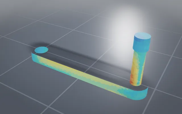
Medical devices — biocompatibility, sterilization, cleanability, labware 15 core entries
rule

ISO 10993-1 body-contact duration categories

Classify device contact by duration before picking materials: limited contact < 24 h, prolonged contact 24 h to 30 days, permanent contact > 30 days — each step up adds required biocompatibility endpoints.

category: limited, max_h: 24 (+2 more rows)

ISO 10993-1 Table A.1 contact-duration categories drive which biological endpoints (cytotoxicity, sensitization, irritation, systemic toxicity, etc.) a device must be evaluated against

Sources: iso-10993-1

material

USP Class VI plastics for patient-contact parts

USP Class VI / ISO 10993 grades commonly specified for patient or drug contact: PC, PSU/PPSU, PEEK, POM-C, silicone, 316L stainless, Ti-6Al-4V and PP — 8 material families cover most rigid, flexible and metal medical parts.

one of PC, PSU/PPSU, PEEK, POM-C, silicone, 316L, Ti-6Al-4V, PP

USP <88> Class VI in-vivo reactivity plus ISO 10993 testing is the baseline grade qualification most medical-device resin and metal suppliers publish against

Sources: usp-class-vi, iso-10993-1

process

Steam autoclave sterilization compatibility

A steam-autoclavable device must survive 121C for 15-20 min (gravity cycle) or 134C for 3-20 min (pre-vacuum cycle); PSU/PPSU, PEEK, PP and 316L tolerate repeated cycles, ABS and POM do not.

121–134 C

ISO 17665-1 moist-heat sterilization cycle parameters and published resin heat-deflection temperatures set which polymers survive repeated autoclaving

Sources: iso-17665-1, ensinger-medical

process

Ethylene oxide (EtO) sterilization compatibility

EtO sterilizes most plastics (PC, ABS, PVC, PP, PA) at 37-63C without heat damage, but a sealed cavity needs a vent path >=1 mm or a porous membrane so residual gas can aerate out over the 8-12 h cycle.

37–63 C

ISO 11135 EtO cycle runs at low temperature so it suits heat-sensitive plastics broadly, but trapped gas in an unvented cavity fails residual-limit testing

Sources: iso-11135

process

Gamma irradiation sterilization compatibility

Gamma sterilization uses a validated dose of 25-50 kGy; PC and stabilised PP hold up, but unstabilised POM and PTFE degrade (chain scission, discolouration, embrittlement) at these doses and should not be gamma-sterilized.

25-50 kGy text

ISO 11137-2 dose-setting methods target a validated sterility assurance level; radiation-stable grades (gamma-stabilised PP, PC) are formulated specifically to survive this dose band

Sources: iso-11137-2, ensinger-medical

rule

Minimum internal radius for cleanable wetted surfaces

Radius every internal corner on a wetted or reprocessed surface to at least 3 mm; a sharper corner traps residue and biofilm that a brush or cleaning fluid cannot reach.

≥ 3 mm

Cleaning-validation guidance for reusable devices treats any internal radius under a few mm as a residue trap that fails a worst-case soil challenge

Sources: iso-13485

rule

No blind pockets or crevices on wetted geometry

A wetted or reprocessed part must have no blind pocket or crevice; where two surfaces must meet, hold the gap to >=1 mm (cleaning fluid can flow through) or 0 mm (a true seal with no gap at all) — nothing in between.

1 mm

A gap narrower than 1 mm traps fluid by capillary action but is too tight for a brush or jet to clear, so cleaning validation treats anything between 0 and 1 mm as a failure mode

Sources: iso-13485

tolerance

Surface roughness for wetted stainless vs. housing surfaces

Hold wetted 316L stainless surfaces to Ra <= 0.8 um so residue and bacteria can't lodge in the finish; a non-wetted housing surface only needs Ra <= 1.6 um.

≤ 1.6 um

Ra 0.8 um is the common pharmaceutical/medical wetted-surface polish floor; a dry housing surface has no cleaning-validation driver so it can stay at a coarser machining/moulding finish

Sources: iso-13485, ensinger-medical

rule

Minimum ingress protection for a medical electrical enclosure

IEC 60601-1 treats an ordinary medical electrical enclosure as needing at least IP21 (protected against solid objects >=12.5 mm and vertically dripping water); a device meant for wipe-down or splash exposure should target IP22 or higher.

one of IP21, IP22, IP54

IP21 is the IEC 60601-1 baseline ingress class for a general medical electrical enclosure with no explicit liquid-exposure claim

Sources: iec-60601-1

dimension

ISO 80369-7 male Luer taper

A male Luer tip runs a 6% taper, outer diameter growing from 4.0 mm at the tip to 4.3 mm over a 7.5 mm engagement length, so it self-seals by friction against the matching female taper.

4–4.3 mm

ISO 80369-7 defines the 6% Luer taper geometry so male and female fittings from different manufacturers seal and disconnect predictably

Sources: iso-80369-7

dimension

SBS/ANSI SLAS microplate footprint

An SBS-format microplate footprint is 127.76 x 85.48 mm, +/-0.5 mm, so it registers on any standard plate reader, washer or liquid handler built to the ANSI/SLAS envelope.

axis: x, value: 127.76 (+1 more rows)

ANSI/SLAS 1-2004 Footprint Dimensions is the interoperability standard every microplate handler, reader and robotic gripper is built against

Sources: ansi-slas-1

dimension

96-well microplate grid pitch and A1 offset

A 96-well SBS microplate uses a 9.0 mm well-to-well pitch on both axes, with well A1 centred at 14.38 mm from the left edge and 11.24 mm from the top edge of the footprint.

9 mm

ANSI/SLAS 4-2004 Well Positions fixes the 9 mm pitch and A1 datum so pipetting heads and readers index every well correctly

Sources: ansi-slas-4

dimension

Microplate overall height by format

A standard SBS microplate stands 14.35 mm tall, a low-profile plate 10.4 mm, and a deep-well plate up to 44 mm — the height a stacker, lid or robotic gripper must clear.

format: standard, height: 14.35 (+2 more rows)

ANSI/SLAS 2-2004 Height Dimensions plus common deep-well plate practice sets the three heights lab automation decks are designed to stack and grip

Sources: ansi-slas-2

dimension

Tube rack bore for 1.5/2.0 mL microtubes

A rack pocket for a 1.5-2.0 mL conical microtube bores 10.8-11.0 mm diameter, tight enough to hold the tube upright without a lid interference, loose enough to drop and pull the tube by hand.

10.8–11 mm

Common 1.5/2.0 mL conical microcentrifuge tube cap-flange outer diameter plus a light hand-insertion clearance

Sources: ensinger-medical

material

Polycarbonate (PC) for medical housings and windows

Medical-grade PC (~1.2 g/cm3) autoclaves and gamma-sterilizes well, is USP Class VI gradeable, and is the default clear or opaque housing resin for reusable diagnostic and monitoring device shells.

1.2 g/cm3

Medical PC grade datasheet density; PC's clarity, impact strength and steam/gamma tolerance make it the default reusable-enclosure resin

Sources: ensinger-medical, usp-class-vi

Mounts & brackets — VESA, tripod, GoPro, wall, shelf, extrusion 17 core entries
dimension

VESA MIS-D mounting pattern (75x75 / 100x100 mm)

MIS-D covers monitors and small TVs: a 75x75 mm or 100x100 mm square hole pattern on the display back, tapped M4, engaging 6-10 mm of thread depth without bottoming on internal components.

75–100, typical 100 mm

VESA FDMI standard hole-pattern family for small/medium displays

Sources: vesa-fdmi

dimension

VESA MIS-E mounting pattern (200x100 mm)

MIS-E covers ultra-wide monitors and small-to-medium TVs: a 200 mm wide x 100 mm tall rectangular hole pattern, tapped M4.

100–200 mm

VESA FDMI standard hole-pattern family for wide displays

Sources: vesa-fdmi

dimension

VESA MIS-F mounting pattern (200x200 mm and up, M6/M8)

MIS-F covers larger TVs: a 200 mm-grid square or rectangular pattern from 200x200 mm up to 800x400 mm and beyond, tapped M6 for panels under about 35 kg or M8 for heavier panels.

200–800 mm

VESA FDMI standard hole-pattern family for large displays

Sources: vesa-fdmi

dimension

1/4-20 UNC tripod thread (small/consumer cameras)

The small camera/tripod thread is 1/4-20 UNC (0.25 in diameter, 20 threads per inch), used on compact cameras, phone mounts and light accessories up to roughly 2-3 kg unsupported.

0.25 in

ISO 1222 / ANSI photographic tripod-connection standard, light-duty thread

Sources: iso-1222-tripod

dimension

3/8-16 UNC tripod thread (heavier cameras, video)

The heavy-duty camera/tripod thread is 3/8-16 UNC (0.375 in diameter, 16 threads per inch), used on video tripods, heads and rigs over roughly 2-3 kg, usually paired with a 1/4-20 reducer bushing.

0.375 in

ISO 1222 / ANSI photographic tripod-connection standard, heavy-duty thread

Sources: iso-1222-tripod

dimension

Arca-Swiss dovetail plate (38 mm, 45 deg)

The classic Arca-Swiss dovetail plate is 38 mm wide with 45-degree bevelled sides, self-centring and wedging tight as the clamp's screw or lever is tightened.

38 mm

Original Arca-Swiss Classic camera-plate dovetail specification

Sources: arca-swiss-usa

dimension

GoPro-style 3-finger mount buckle geometry

The GoPro 3-prong buckle runs about a 3 mm gap between fingers, about 15 mm of finger engagement length, and a roughly 5.1 mm pivot-pin bore clamped by an M5-class thumbscrew; match the gap and bore before mating to third-party accessories.

param: finger-gap, value: 3 (+2 more rows)

Published reverse-engineered GoPro buckle dimensions used throughout the parametric-mount design community

Sources: gopro-mount-geometry

dimension

Phone clamp jaw travel range

A phone mount's spring or screw clamp should open 55-95 mm to cover phones from compact to large phablets/foldables in their cases, with 3-5 mm of extra rubber-pad compression at each end.

55–95 mm

Common universal phone-clamp jaw travel range across current mount hardware

Sources: gopro-mount-geometry

dimension

Bicycle handlebar clamp diameters

Common handlebar clamp diameters are 22.2 mm (flat/riser bar grip area), 25.4 mm (older MTB stem clamp), 31.8 mm (modern oversized standard) and 35 mm (wide-bar performance stems) — match the mount bore to the bar's stated clamp diameter, not its grip-area diameter.

d: 22.2 (+3 more rows)

Bicycle industry handlebar clamp-diameter convention

Sources: bike-diameter-standards

dimension

Bicycle seatpost diameters

Common seatpost diameters are 27.2 mm (road, most compliant), 30.9 mm and 31.6 mm (mountain/gravel, most common with dropper posts); a seatpost-mount clamp or light bracket must match the frame's stated diameter exactly, not round to a neighbouring size.

d: 27.2 (+2 more rows)

Bicycle industry seatpost-diameter convention

Sources: bike-diameter-standards

dimension

Bracket wall/arm thickness, 6061-T6 aluminium

A load-bearing 6061-T6 bracket arm runs 3-6 mm thick for hand-tool-scale consumer mounts (VESA, camera, shelf up to about 5 kg), thickening toward 6-10 mm for TV-class or cantilevered loads; a thinner section should add a rib or gusset rather than relying on material alone.

3–10, typical 3 mm

Common CNC/waterjet bracket gauge for aluminium load paths at consumer-mount scale

Sources: matweb-6061-t6

dimension

Bracket wall thickness, mild steel

A load-bearing mild-steel bracket runs 2-4 mm thick (laser-cut/press-brake sheet) for shelf and wall-mount brackets, powder-coated after forming; steel's higher stiffness lets it run thinner than an equivalent aluminium arm for the same deflection.

2–4, typical 2 mm

Common laser-cut/press-brake bracket gauge for mild steel sheet

Sources: astm-a1011

rule

Shelf bracket load vs arm length (cantilever)

A shelf bracket is a cantilever: stress and tip deflection scale with arm length cubed, so doubling the arm length roughly halves the safe load — keep arm-length-to-thickness under about 15:1 for a solid arm, or add a gusset beyond that.

≤ 15 ratio

Cantilever beam bending theory (deflection scales with L^3/t^3): L/t is the practical proxy DFM guides use for when a plain arm needs bracing

Sources: matweb-6061-t6

rule

L-bracket inside-corner gusset rule

Gusset (fill or rib) the inside corner of an L-bracket rather than leaving a sharp 90-degree step: a diagonal gusset or triangular rib spanning at least 30-50% of each leg's length cuts the peak bending stress at the corner by roughly half compared with an ungusseted step.

30–50 %

A sharp inside corner is the stress-concentration point on a bent or welded L-bracket under load; a gusset spreads the load path across a longer section

Sources: astm-a1011

rule

Inside corner fillet on a machined or printed mount

Fillet every inside corner of a mount or bracket to at least 0.5-1x the local wall/arm thickness and never leave it sharp: a sharp inside corner is the single most common fatigue-crack start point on a repeatedly loaded bracket.

0.5–1 ratio

Standard stress-concentration/fatigue-crack-initiation avoidance at re-entrant corners

Sources: matweb-6061-t6

fastener

Drywall wall-anchor sizing for a wall mount

Into bare drywall use a #8 screw with a 6 mm (1/4 in) expansion or self-drilling plastic plug, rated 15-25 kg per anchor depending on drywall thickness; space anchors at least 150-200 mm apart and keep every anchor hole at least 10 mm from a board edge or another fastener.

15–25 kg

Standard plastic drywall-anchor pullout rating and the edge/spacing distance that avoids crushing the gypsum core between anchors

Sources: drywall-anchor-guide

dimension

2020 aluminium extrusion T-slot (6 mm slot, M5 T-nut)

A 20x20 mm (2020) T-slot extrusion carries a 6 mm-wide T-slot on each face sized for an M5 drop-in T-nut; a bracket that clamps onto the rail should not exceed roughly 60% of the rail's face width so clamping material remains on either side.

6 mm

Common 20-series T-slot extrusion and T-nut sizing across major suppliers

Sources: tnutz-2020-extrusion

Peripherals — keyboards, mice, controllers, headsets 16 core entries
dimension

Standard MX key pitch (19.05 mm / 0.75 in)

Full-size mechanical key units sit on a 19.05 mm (0.75 in) grid in both X and Y; a 1u key occupies one grid cell and wider keys (2u, 6.25u spacebar) are integer or near-integer multiples of this pitch.

19.05 mm

Inherited from IBM Model M / typewriter key spacing; every MX-compatible keycap set and plate/PCB CAD tool assumes this grid.

Sources: keyboard-plate-guide, qmk-hardware-guide

dimension

Choc low-profile key pitch (18 x 17 mm)

Kailh Choc low-profile keyboards commonly use an 18 mm (X) x 17 mm (Y) pitch instead of the MX 19.05 mm grid, though some Choc boards keep 19.05 mm X-pitch and tighten only Y.

axis: X, mm: 18 (+1 more rows)

Choc's shorter travel and smaller housing let designers tighten the grid for a more compact board; 18x17 is the de-facto community convention, not an official Kailh spec.

Sources: kailh-choc-datasheet, keyboard-plate-guide

dimension

MX switch plate cutout (14.0 x 14.0 mm, +0.05 mm)

Cherry MX and MX-compatible switches need a 14.0 x 14.0 mm square plate cutout with +0.05 mm positive tolerance (14.00-14.05 mm) so the switch's plate clips seat without being loose enough to rattle.

14–14.05, typical 14.02 mm

Cherry's own mounting-plate drawing specifies 14.0 mm square with the switch housing's clip ribs sized for a light press fit at +0.05 mm.

Sources: cherry-mx-datasheet, keyboard-plate-guide

dimension

Choc switch plate cutout (~14.5 x 14.5 mm)

Kailh Choc v1/v2 switches use a slightly larger square plate cutout, commonly cut 14.4-14.5 mm per side (looser than MX's 14.0 mm) because the Choc housing's retention ribs are shallower.

14.4–14.5, typical 14.45 mm

Community-measured convention across open-source Choc plate files; Kailh does not publish as tight a cutout tolerance as Cherry does for MX.

Sources: kailh-choc-datasheet, keyboard-plate-guide

dimension

Switch plate thickness (1.5 mm typical)

Keyboard switch plates run 1.2-1.6 mm thick depending on material; 1.5 mm is the most common thickness across steel, aluminium, FR4 and polycarbonate plates and is what most switch clip geometry assumes.

1.2–1.6, typical 1.5 mm

Cherry's clip-rib height and standard plate mounting drawings assume ~1.5 mm engagement; thinner plates reduce clip retention, thicker plates need the switch pins to still reach the PCB.

Sources: cherry-mx-datasheet, keyboard-plate-guide

dimension

Plate-to-PCB spacing, MX (5.0 mm)

The gap from the underside of an MX switch plate to the top of the PCB is 5.0 mm — the distance MX switch pins and stem travel through before soldering onto the board.

5 mm

Fixed by Cherry MX's housing height below the plate-retention clips; case standoffs and PCB mounting posts are dimensioned around this 5 mm gap.

Sources: cherry-mx-installation-guide, keyboard-plate-guide

dimension

Plate-to-PCB spacing, Choc (3.4 mm)

Kailh Choc's shorter low-profile housing needs only 3.4 mm from plate underside to PCB top, versus 5.0 mm for MX — the main reason Choc boards can be built thinner.

3.4 mm

Set by the Choc housing height below its plate clips; used across open-source Choc case/standoff designs.

Sources: kailh-choc-datasheet, keyboard-plate-guide

dimension

Cherry-style stabilizer plate cutout, 2u key (Costar/Cherry)

A 2u key (backspace, tab, etc.) needs a Cherry-style stabilizer cutout: a 3.0 mm wide slot with wire-post holes spaced 23.8 mm either side of the switch cutout centre.

23.8 mm

Cherry-style stabilizer geometry is the de-facto standard adopted by nearly every plate/PCB design tool (KLE, plate generators).

Sources: keyboard-plate-guide, cherry-mx-installation-guide

dimension

Keyboard case wall thickness (2-4 mm)

Injection-moulded or CNC keyboard case walls run 2-4 mm: 2-2.5 mm for a moulded ABS/PC shell, 3-4 mm for a CNC'd aluminium case that also needs to resist flex under typing force.

2–4, typical 3 mm

Below ~2 mm a moulded shell warps and an aluminium case rings/flexes; above 4 mm adds weight and cost with no stiffness benefit for a desktop keyboard.

Sources: keyboard-plate-guide

dimension

Keyboard typing angle (3-8 degrees)

A keyboard's typing angle — the front-to-back tilt of the key plane — runs 3-8 degrees for most boards; flip-out feet typically add 2-4 degrees on top of a 3-6 degree built-in base angle.

3–8, typical 6 deg

Angles above ~8-10 degrees increase wrist extension and RSI risk; most ergonomic guidance recommends keeping the wrist closer to neutral, favouring the low end of this range or a negative-tilt/tented design.

Sources: bifma-g1, keyboard-plate-guide

dimension

USB-C port cutout (9.0 x 3.3 mm)

A USB-C receptacle case cutout is 9.0 mm wide x 3.3 mm tall to clear the connector shell; the daughterboard carrying it is usually screwed or slotted to the case wall independent of the main PCB so cable-insertion force never loads switch-side solder joints.

[object Object] mm

9.0 x 3.3 mm matches the USB Type-C receptacle shell outline per the USB-IF connector spec, plus a small clearance margin for case tolerance.

Sources: usb-c-spec

dimension

Mouse dimensions for palm grip

Palm-grip mice (whole hand rests on the shell) run larger: length 120-130 mm, width 62-70 mm, height (rear hump) 38-45 mm — tall enough for the palm to sit on the hump rather than hover above it.

axis: length, min_mm: 120, max_mm: 130 (+2 more rows)

Palm grip needs a tall rear hump and long shell so the whole hand (not just fingertips) is supported, unlike claw/fingertip grips which favour a lower, shorter shell.

Sources: mouse-grip-ergonomics-study

dimension

Mouse dimensions for claw grip

Claw-grip mice (arched fingers, palm barely touching) suit a shorter, lower shell: length 110-120 mm, width 58-65 mm, height 34-40 mm, often with a steeper front slope for the fingertips to hook over the front edge.

axis: length, min_mm: 110, max_mm: 120 (+2 more rows)

A lower rear hump and shorter length keep the palm from needing to fully rest, matching the arched-finger claw posture.

Sources: mouse-grip-ergonomics-study

dimension

Main button travel and pre-travel

Main mouse buttons have 1.5-2.5 mm total travel with 0.3-0.8 mm pre-travel (movement before the switch clicks); the shell's flexure button arm is tuned in thickness (0.6-1.0 mm) to give this travel without fatiguing before the switch's rated cycle life.

1.5–2.5, typical 2 mm

Pre-travel and total travel are dominated by the shell's button-arm flexure design, not the micro switch itself, which typically actuates over <1 mm of its own plunger movement.

Sources: omron-d2fc-datasheet, kailh-gm-datasheet

dimension

Mouse shell wall thickness

Injection-moulded mouse shell walls run 1.2-1.8 mm — thin enough to mould without sink marks or long cooling times, thick enough to resist flex under grip pressure and to survive the 1 m drop test at unsupported spans.

1.2–1.8, typical 1.5 mm

Sits in the general thin-wall injection-moulding sweet spot; ribs and bosses (not thicker walls) carry the extra local stiffness a shell needs at screw points and the button-arm root.

Sources: gaming-mouse-durability-standard

dimension

Controller handgrip diameter

Console-style controller handgrips (the cylindrical/tapered section under each hand) run 34-40 mm across at their widest, tapering to 28-32 mm near the top where the fingers curl around the trigger housing.

28–40, typical 36 mm

Sized to fill an adult palm without over-extending the fingers to reach the face buttons/sticks on top, based on measured teardown dimensions of mainstream console controllers.

Sources: controller-ergonomics-reference

Piping -- pipe, tube, fittings, flanges, manifolds, O-rings and ducting 16 core entries
dimension

NPS 1/2-4 outside diameters and DN equivalents

Steel pipe OD runs 21.3, 26.7, 33.4, 42.2, 48.3, 60.3, 73.0, 88.9, 114.3 mm for NPS 1/2, 3/4, 1, 1-1/4, 1-1/2, 2, 2-1/2, 3, 4 (DN15, 20, 25, 32, 40, 50, 65, 80, 100) -- OD is fixed by NPS, wall thickness by schedule.

one of 21.3, 26.7, 33.4, 42.2, 48.3, 60.3, 73, 88.9, 114.3

ASME B36.10 pipe OD series, the fixed-OD convention every NPS schedule wall is cut from

Sources: asme-b31.3

dimension

Metric hydraulic/pneumatic tube OD series

Metric tube for hydraulic and pneumatic lines is stocked at 6, 8, 10, 12, 16, 20, 25 mm OD with 1-2 mm wall depending on pressure class -- match the fitting's tube-OD rating exactly, tube fittings do not tolerate an oversize or undersize tube.

one of 6, 8, 10, 12, 16, 20, 25

Swagelok/Parker metric tube catalogue OD series for compression and flare tube fittings

Sources: swagelok-tubing-data

dimension

ASME B16.5 Class 150 NPS 2 flange (typical)

An NPS 2 Class 150 flange is 152.4 mm OD, 120.7 mm bolt circle, four dia19.1 mm bolt holes and a 1.6 mm raised face -- the size to reach for when a fitting needs one flange dimension; see pipe-schedule-wall-table for the full NPS 1-4 table.

field: OD, value: 152.4 (+4 more rows)

ASME B16.5 Class 150 dimension table, NPS 2 row

Sources: asme-b16.5

dimension

NPT taper pipe thread: 1/4 and 1/2 NPT

1/4 NPT is 18 TPI, tap drill 7/16 in (11.1 mm); 1/2 NPT is 14 TPI, tap drill 45/64 in (17.9 mm) -- both taper 1:16 on diameter, so a straight (non-tapered) hole will not seal an NPT fitting.

size: 1/4 NPT, tpi: 18, drillIn: 7/16, drillMm: 11.1 (+1 more rows)

ASME B1.20.1 NPT thread table (TPI, pitch diameter) and taper convention

Sources: asme-b1-20-1

dimension

BSPP (G) parallel thread: G1/4, G3/8, G1/2

G1/4 major dia 13.157 mm at 19 TPI, tap drill 11.4 mm; G3/8 major dia 16.662 mm at 19 TPI; G1/2 major dia 20.955 mm at 14 TPI, tap drill 18.6 mm -- parallel (straight) thread, sealed by a bonded washer or O-ring, not by the thread itself.

size: G1/4, majorMm: 13.157, tpi: 19, drillMm: 11.4 (+2 more rows)

ISO 228-1 BSPP thread dimension table

Sources: iso-228-1

dimension

O-ring face-seal groove depth/width by AS568 cross-section

Face-seal groove sized to the O-ring cross-section: CS 1.78 mm (AS568 -010/-014/-020) -> depth 1.3, width 2.5; CS 2.62 mm (-113) -> depth 2.0, width 3.6; CS 3.53 mm (-210) -> depth 2.7, width 4.8 mm.

csMm: 1.78, examples: -010/-014/-020, depthMm: 1.3, widthMm: 2.5 (+2 more rows)

Parker O-Ring Handbook static face-seal groove design tables, ISO 3601-2 housing series

Sources: parker-oring-handbook, iso-3601-2

rule

O-ring squeeze, stretch and groove fill targets

Design 15-25% squeeze (cross-section compression) on a static groove, 2-5% stretch on a piston/rod bore fit, and 70-90% groove fill by volume -- below the range the seal leaks, above it the O-ring extrudes into the clearance gap or takes a compression set.

15–25 %

Parker O-Ring Handbook and ISO 3601-2 squeeze/stretch/fill design envelope

Sources: parker-oring-handbook, iso-3601-2

rule

Barlow's formula for pipe/manifold wall thickness

Minimum wall t = P*D/(2*S*E) -- pressure times diameter over twice the allowable stress times joint efficiency; e.g. a 10 mm bore at 10 MPa in 6061-T6 (S~69 MPa, E=1 solid block) needs only t~0.7 mm by burst alone, which is why manifold-wall-min (5 mm) governs instead.

t = P*D/(2*S*E) mm

ASME B31.3 wall-thickness design equation (Barlow's formula form)

Sources: asme-b31.3

rule

Minimum manifold block wall between a port and an outside face

Leave >= 5 mm of solid aluminium wall between any drilled port and the block's outside face (or another port) at 10 MPa working pressure -- Barlow's formula alone under-predicts the wall a drilled, threaded, cyclically loaded manifold needs.

≥ 5 mm

Common hydraulic/pneumatic manifold design-guide minimum wall for a 10 MPa aluminium block, above the Barlow-formula burst minimum

Sources: engineering-toolbox

rule

Minimum port-to-port spacing in a manifold

Space adjacent manifold ports at least 1.5x the larger port's diameter, centre to centre, so the wall between two drilled/tapped holes has enough material to resist cracking under pressure and tapping torque.

≥ 1.5 ratio

Common hydraulic manifold design-guide minimum port spacing to avoid thin webs between drilled/tapped holes

Sources: engineering-toolbox

rule

Minimum pipe/port thread engagement

Engage a tapped pipe or port thread at least 1x the nominal thread diameter in length -- NPT also needs full hand-tight-plus-turns engagement for its taper to seal; shallower engagement strips under torque or leaks past incomplete taper contact.

≥ 1 ratio

Common pipe-thread engagement guidance for tapped ports in metal (ASME B1.20.1 practice)

Sources: asme-b1-20-1

rule

Hose barb OD sizing

Size a hose barb's OD 10-15% larger than the hose's nominal inside diameter so the hose stretches on and grips -- undersize and it weeps under pressure, oversize and the hose splits or won't push on.

10–15 %

Common hose-barb fitting design guidance (Parker/Swagelok barb catalogues)

Sources: swagelok-tubing-data

rule

Target flow velocity: liquid vs air lines

Size pipe/tube bore for 1-3 m/s liquid velocity (water, hydraulic oil) and 10-20 m/s for compressed air/gas -- undersizing either raises pressure drop and noise/erosion, oversizing wastes material and slows response.

service: liquid, minMs: 1, maxMs: 3 (+1 more rows)

Engineering ToolBox recommended flow-velocity ranges for liquid and compressed-gas piping

Sources: engineering-toolbox

dimension

Round HVAC duct sizes (EN 1506)

Round sheet-metal duct is stocked at 100, 125, 150, 200, 250 and 315 mm diameter -- pick from this series rather than an arbitrary bore so off-the-shelf elbows, tees and dampers fit.

one of 100, 125, 150, 200, 250, 315

EN 1506 standard round sheet-metal duct diameter series

Sources: en-1506

material

6061-T6 aluminium for manifold blocks

6061-T6 is the default manifold/block material for hydraulic and pneumatic circuits under ~20-25 MPa: yield 276 MPa, density 2.70 g/cm3, machines and anodizes cleanly, and takes a drilled/tapped port without cracking at the wall minimums in this pack.

property: yield, value: 276, unit: MPa (+1 more rows)

MatWeb 6061-T6 property data, the standard machined manifold alloy

Sources: matweb-materials

material

316L stainless for wetted fittings and valve bodies

316L stainless (yield ~170 MPa annealed, density 8.0 g/cm3) is the default corrosion-resistant wetted material for fittings, valve bodies and process tube where the fluid or environment attacks carbon steel or brass.

property: yield, value: 170, unit: MPa (+1 more rows)

MatWeb 316L stainless property data, the standard corrosion-resistant process-fluid material

Sources: matweb-materials

Power transmission — gears, sprockets, racks, cams, cranks, belts 18 core entries
dimension

Full-depth 20° involute spur gear standard proportions

Standard 20° full-depth system: addendum = 1.0 m, dedendum = 1.25 m, whole depth = 2.25 m, clearance = 0.25 m, where m is module in mm — the four numbers that turn a module + tooth count into a buildable tooth.

feature: addendum, multiplierOfModule: 1 (+3 more rows)

AGMA 201.02 / ISO 21771 full-depth 20° proportional system, the default for cut and printed spur gearing

Sources: iso-21771

dimension

Spur gear pitch, base, outer and root diameter formulas

Pitch dia D = m·N; base dia Db = D·cos(20°); outer (tip) dia Do = m(N+2); root dia Dr = m(N-2.5) — 4 formulas from module m and tooth count N that fix every circle on the gear.

circle: pitch, formula: D = m*N (+3 more rows)

Direct consequence of the 1.0m/1.25m addendum/dedendum standard proportions applied to the pitch circle D = m*N

Sources: iso-21771

dimension

Spur gear circular tooth thickness at the pitch circle

Nominal circular tooth thickness at the pitch circle t = pi*m/2 — half the circular pitch (p = pi*m); a module-2 tooth is 3.1416 mm thick at the pitch line before backlash allowance is subtracted.

t = PI*m/2 mm

Standard tooth-to-space symmetry: tooth thickness equals space width equals half the circular pitch p = pi*m

Sources: iso-21771

rule

Profile shift coefficient to avoid undercut below 17 teeth

For a 20deg pinion with N < 17 teeth, shift the generating rack outward by coefficient x = (17-N)/17 (in units of module) to eliminate root undercut instead of accepting a weak, undercut tooth — an 8-tooth pinion needs x = 0.53.

x = (17-N)/17 ratio

Minimum profile-shift coefficient that keeps the involute generated by a rack cutter from undercutting a 20deg-pressure-angle pinion below the 17-tooth limit

Sources: iso-21771

dimension

Helical gear helix angle and normal/transverse module

Helix angles run 15-30deg (20-25deg typical); normal module mn (the cutter's module) relates to transverse module mt by mn = mt*cos(helix) — model the tooth profile in the normal plane, then wrap it around the cylinder at the helix angle.

15–30, typical 20 deg

Common helical-gear helix-angle range balancing axial thrust load against the smoother, quieter engagement a higher angle gives

Sources: shigley-mech-design

rule

Tredgold approximation for bevel gear tooth form

Treat a straight bevel gear's tooth as an equivalent spur gear with formative tooth count Nf = N/cos(gamma), gamma the pitch cone angle — a 20-tooth bevel pinion at a 30deg cone angle behaves, for strength and cutter selection, like a 23.1-tooth spur gear.

Nf = N/cos(gamma) count

Tredgold's approximation: the back-cone development of a bevel tooth is (very nearly) a spur tooth of the formative count, letting spur-gear strength and cutter tables apply to bevels

Sources: agma-2005-d03

dimension

Bevel gear pitch cone angle for 90-degree shafts

For gears on shafts at 90deg, pitch cone angle gamma1 = atan(N1/N2) for gear 1 (gamma2 = 90deg - gamma1) — a 1:1 mitre bevel pair sits at 45deg each; a 2:1 pair sits at 26.6deg (pinion) and 63.4deg (gear).

gamma1 = atan(N1/N2) deg

Pitch cones of two bevel gears share an apex; for perpendicular shafts the cone half-angles sum to 90deg in the ratio of the tooth counts

Sources: agma-2005-d03

rule

Worm lead angle and the self-locking threshold

Lead angle lambda = atan(lead/(pi*Dworm)); a steel-worm/bronze-wheel drive with lambda below about 5deg is self-locking (the wheel cannot back-drive the worm) at typical 0.05-0.10 sliding friction coefficients — above roughly 11deg it will not self-lock.

≤ 5 deg

Self-locking requires the lead angle to stay below the friction angle (atan(mu)); mu = 0.05-0.10 for a run-in bronze/steel worm mesh gives a friction angle of about 3-6deg

Sources: agma-6034-b92

dimension

Worm gear ratio from wheel teeth and worm starts

Ratio = Nwheel / Nstarts; a single-start worm (Nstarts=1) driving a 40-tooth wheel gives 40:1 in one mesh, but halves to 20:1 or 13.3:1 if a double- or triple-start worm (2 or 3 starts) is substituted for the same wheel.

ratio = Nwheel/Nstarts ratio

Each worm revolution advances the wheel by (starts) teeth, so the ratio is the wheel tooth count divided by the worm's thread-start count

Sources: agma-6034-b92

rule

Planetary gear ring/sun/planet tooth-count meshing condition

For a sun, planets and ring at one common module, the ring tooth count must equal Nr = Ns + 2*Np (sun plus twice the planet count) so the planet meshes with both the sun and the ring at the same centre distance.

Nr = Ns + 2*Np count

The planet's centre sits midway between sun and ring centres; equal module and equal centre distance to both forces this tooth-count relation

Sources: shigley-mech-design

rule

Planetary gear assembly condition for k equally spaced planets

k equally spaced planets assemble only if (Ns + Nr) / k is a whole number — a 20-tooth sun with a 60-tooth ring (sum 80) assembles with 2 or 4 planets but not 3, since 80/3 is not an integer.

(Ns+Nr) mod k == 0 ratio

Each planet must land on a tooth of both sun and ring when placed at its 360/k angular station; failing the divisibility test means the last planet cannot mesh

Sources: shigley-mech-design

dimension

ANSI roller chain pitch by chain number (#25/#35/#40)

ANSI/ASME B29.1 chain number is 1/8 inch of pitch: #25 = 6.35 mm (1/4in) pitch, #35 = 9.525 mm (3/8in), #40 = 12.7 mm (1/2in) — the pitch every sprocket tooth-spacing formula in this pack takes as p.

chain: #25, pitchMm: 6.35, rollerOrBushingMm: 3.3, note: bushing chain, no roller (+2 more rows)

ASME B29.1 precision roller chain dimension table

Sources: asme-b29-1

dimension

Rack tooth profile: straight flanks at the pressure angle

A rack tooth is straight-sided (not curved): total tooth height 2.25 m (1.0 m addendum above the pitch line + 1.25 m dedendum below), flanks straight at the 20deg pressure angle from the tooth's vertical centreline, mating any pinion of the same module.

height = 2.25*m mm

A rack is a gear of infinite radius: its involute flank degenerates to a straight line at the pressure angle, which is why one rack meshes with pinions of any tooth count at the same module

Sources: iso-21771

dimension

Classical V-belt cross-section dimensions (A/B/C)

ISO 4184 classical V-belt sections: A = 13 x 8 mm (top width x height), B = 17 x 11 mm, C = 22 x 14 mm — pick the section from the sheave's groove angle (typically 34-38deg) and the pulley pitch diameter range the section is rated for.

section: A, topWidthMm: 13, heightMm: 8 (+2 more rows)

ISO 4184 / RMA IP-22 classical V-belt cross-section standard

Sources: iso-4184

dimension

Timing belt tooth pitch: HTD 3M/5M/8M and T5/T2.5

Curvilinear HTD belts run 3, 5 or 8 mm tooth pitch (HTD3M/5M/8M); trapezoidal-tooth belts run T2.5 (2.5mm) or T5 (5mm) pitch with about 1.2 mm tooth height at T5 — match the belt pitch to the pulley tooth pitch exactly, they are not interchangeable.

one of HTD3M, HTD5M, HTD8M, T2.5, T5

Gates HTD curvilinear tooth series and the ISO 5296 trapezoidal T-series, the two common synchronous-belt tooth families outside 3D-printer-scale GT2

Sources: gates-htd-manual, iso-5296

rule

Crankshaft stroke equals twice the crank throw

Piston/slider stroke = 2 x throw, where throw is the crank radius (the offset of the crankpin centre from the main-journal axis) — a 40 mm throw gives an 80 mm stroke; get the throw wrong by half and the stroke is wrong by exactly double that.

stroke = 2*throw mm

Simple kinematics of a slider-crank: the slider travels from one extreme (crankpin at top dead centre) to the other (bottom dead centre), a distance of twice the crank radius

Sources: shigley-mech-design

dimension

RC servo output spline tooth count and diameter by brand

Standard-size hobby servo splines: 25T (Futaba/Hobbico/Savox, ~5.9mm OD; MG996R clone 5.8mm), 24T (Hitec, ~5.9mm), 23T (JR/Sanwa/Spektrum, ~5.9mm) — match the horn's tooth count to the brand, they are not interchangeable.

brand: Futaba/Hobbico/Savox, teeth: 25, splineOdMm: 5.9 (+3 more rows)

RC hobby servo brands standardised on incompatible spline tooth counts within the same standard-size servo envelope; RobotDigg's spline chart cross-references brand to tooth count

Sources: robotdigg-servo-spline

tolerance

ISO 286 H7 hole tolerance by nominal bore size

H7 (a hole with zero lower deviation) grows with size: +12/0 um at 3-6mm, +15/0 um at 6-10mm, +18/0 um at 10-18mm, +21/0 um at 18-30mm — the default reamed/bored fit for a bearing housing or a shaft's mating bore.

rangeMm: 3-6, upperUm: 12, lowerUm: 0 (+3 more rows)

ISO 286-2 IT7 grade tolerance values applied to the H fundamental-deviation (hole basis, lower deviation zero)

Sources: iso-286-2

Robotics -- shafts, bearings, gears, belts, motors and linkages 18 core entries
dimension

Standard robotics shaft diameters (h6/h7)

Common robot shaft/axle diameters are 3, 4, 5, 6, 8, 10, 12, 15 and 20 mm, turned to h6 (precision bearing/pulley register) or h7 (looser register, e.g. printed hubs) per ISO 286.

one of 3, 4, 5, 6, 8, 10, 12, 15, 20

ISO 286 shaft tolerance classes: h6 for a bearing-seat register, h7 where the mating bore is coarser (3D-printed hub, clamp coupling)

Sources: iso-286

fastener

Parallel keyway width/height/depth by shaft diameter (DIN 6885)

DIN 6885-1 parallel keys by shaft dia: 6->2x2 (t1 1.2), 8->2x2 (t1 1.2), 10->3x3 (t1 1.8), 12->4x4 (t1 2.5), 15->5x5 (t1 3.0), 20->6x6 (t1 3.5) mm -- b x h key cross-section, t1 the shaft-side depth.

shaftDia: 6, b: 2, h: 2, t1: 1.2 (+5 more rows)

DIN 6885-1 form B square-ended parallel key table, keyed by shaft diameter range

Sources: din-6885

feature

D-flat depth for set-screw shaft retention

A milled D-flat for a set screw (common on 5 mm NEMA 17 and small gearmotor shafts) is cut 0.5-1.0 mm deep, centred on the shaft so the set screw seats flat rather than point-loading round stock.

0.5–1, typical 0.7 mm

Common hobby-drivetrain practice for stepper and gearmotor output shafts (StepperOnline mechanical drawings show a flat on the 5mm/6.35mm shaft)

Sources: stepperonline-nema-mech

dimension

Common robotics deep-groove ball bearing sizes (bore x OD x width)

Bearings used across robot joints: 608 8x22x7, 6000 10x26x8, 6001 12x28x8, 6002 15x32x9, 6004 20x42x12, 623 3x10x4, 625 5x16x5, 626 6x19x6, 688 8x16x5, MR105 5x10x4 (all mm).

designation: 608, bore: 8, od: 22, width: 7 (+9 more rows)

SKF Rolling Bearings Catalogue dimension tables for the 60x/62x/68x deep-groove series and MR miniature series

Sources: skf-bearing-catalogue

tolerance

Bearing housing bore and shaft fit classes

House the outer ring in an H7 bore. Fit the shaft: k6 where the inner ring rotates with the shaft (a light interference press, the normal robot-joint case), h6 where the shaft is stationary and the outer ring/housing rotates (a sliding fit).

one of H7 housing / k6 shaft (rotating inner ring), H7 housing / h6 shaft (rotating outer ring)

SKF fit-selection guidance (rotating-inner-ring load case) applied to ISO 286 shaft/hole tolerance classes

Sources: skf-bearing-catalogue, iso-286

dimension

Gear module and pressure angle for small robot gearing

Robot gearing is cut to module 0.5, 1, 1.5 or 2 mm at a 20deg pressure angle -- the standard KHK/AGMA rack, so off-the-shelf gears and hobs interchange across vendors.

one of 0.5, 1, 1.5, 2

KHK gear technical reference: standard module series and the 20deg full-depth involute rack

Sources: khk-gear-tech-ref

rule

Minimum tooth count before undercut (20deg pressure angle)

A 20deg pressure-angle involute gear needs >= 17 teeth to avoid root undercut from rack generation; a pinion below 17 teeth loses root strength unless profile-shifted.

≥ 17 count

KHK gear technical reference: undercut limit z_min = 2/sin^2(pressure angle) ~= 17.1 for 20deg

Sources: khk-gear-tech-ref

rule

Spur gear centre distance

Two spur gears of the same module mesh at centre distance a = m(z1+z2)/2 -- module times the summed tooth counts, halved; get the module or a tooth count wrong and the mesh either binds or runs with excess backlash.

a = m*(z1+z2)/2 mm

Standard involute spur-gear meshing geometry (KHK gear technical reference)

Sources: khk-gear-tech-ref

dimension

GT2 pulley pitch diameter from tooth count

A GT2 (2 mm pitch) pulley's pitch diameter is PD = z*2/pi mm -- a 20-tooth pulley pitches at 12.73 mm, a 16-tooth at 10.19 mm; the belt centreline sits on this circle, not the pulley OD.

PD = z*2/pi mm

Gates PowerGrip GT2 design manual: pitch diameter = teeth x pitch / pi

Sources: gates-gt2-design-manual

dimension

GT2 belt widths

GT2 timing belt comes 6 mm or 9 mm wide for light robotics use; match the pulley's flange width to the belt or it walks off the pulley under any side load.

one of 6, 9

Gates PowerGrip GT2 design manual standard belt width series

Sources: gates-gt2-design-manual

dimension

NEMA 17 stepper mounting pattern

NEMA 17 motors present a 42.3 mm square face, four M3 holes on a 31 mm bolt square, a dia22 mm central pilot boss, and (usually) a dia5 mm output shaft.

field: faceSquare, value: 42.3 (+4 more rows)

NEMA ICS 16 frame-size convention as realised in NEMA 17 stepper mechanical drawings (StepperOnline)

Sources: nema-ics-16, stepperonline-nema-mech

dimension

NEMA 23 stepper mounting pattern

NEMA 23 motors present a 56.4 mm square face, four bolts on a 47.14 mm square, a dia38.1 mm central pilot boss, and a dia6.35 mm (1/4 in) output shaft.

field: faceSquare, value: 56.4 (+3 more rows)

NEMA ICS 16 frame-size convention as realised in NEMA 23 stepper mechanical drawings (StepperOnline)

Sources: nema-ics-16, stepperonline-nema-mech

dimension

Tr8 trapezoidal lead-screw pitch and lead options

An 8 mm trapezoidal lead screw is cut Tr8x2 (single-start, 2 mm lead = 2 mm pitch, self-locking) or Tr8x8 (4-start, 8 mm lead, 2 mm pitch, fast but not self-locking) -- same thread form, very different travel per revolution.

designation: Tr8x2, pitch: 2, lead: 2, starts: 1 (+1 more rows)

ISO 724 metric trapezoidal thread basic dimensions, applied to the Tr8 hobby lead-screw sizes sold with these two lead options

Sources: iso-724-trapezoidal

dimension

Flexible shaft coupling bore combinations

Motor-to-leadscrew couplings for hobby robotics are stocked as 5x8 mm and 6.35x8 mm bore pairs (NEMA 17's 5 mm or a 1/4 in shaft into an 8 mm lead screw), body OD 19-25 mm.

one of 5x8, 6.35x8

Common jaw/beam coupling catalogue bore pairings for stepper-to-leadscrew drivetrains

Sources: stepperonline-nema-mech

tolerance

Position tolerance for a machined bearing bore

Hold a CNC-machined bearing bore or shaft register to +-0.05 mm position; the same feature on an FDM print only holds +-0.2 mm, so a press-fit bearing pocket sized for CNC will rattle or crack a printed part.

one of [object Object], [object Object]

ISO 286-class positional capability difference between 3-axis CNC and FDM printing

Sources: iso-286

material

Shaft steels: 1045 and 4140

Turned robot shafts and axles use 1045 (cold-drawn, good machinability, adequate wear resistance unshielded) or 4140 (alloy steel, through-hardenable, used for higher-load or ground shafts); both take a keyway and press-fit bearings without distortion.

material: 1045 (normalized), yield_MPa: 375, hardness_HB: 170 (+1 more rows)

MatWeb property data for AISI 1045 and 4140 bar stock, the two steels most robot shafting is cut from

Sources: matweb-materials

material

POM (acetal) for machined and printed gears

POM (Delrin/acetal) is the default plastic gear material: low friction against itself and steel, dimensionally stable, and machines or injection-molds to a clean tooth profile -- density 1.41 g/cm3, tensile ~65 MPa.

property: density, value: 1.41, unit: g/cm3 (+1 more rows)

MatWeb POM copolymer property data, the standard plastic gear/bushing material

Sources: matweb-materials

material

3D-printed structural robot parts: PA12 and CF-PA

Load-bearing printed brackets, arms and gear housings favour PA12 (SLS nylon, tough, low warp) or carbon-fibre-reinforced PA (CF-PA, higher stiffness, lower creep) over PLA/PETG when the part carries a running joint load.

material: PA12 (SLS), tensile_MPa: 48, flex_modulus_MPa: 1500 (+1 more rows)

MatWeb PA12 (SLS) and CF-filled PA property data versus unfilled FDM plastics for load-bearing service

Sources: matweb-materials

Sheet metal — brackets, enclosures, racks and press-brake formed parts 16 core entries
dimension

Sheet gauge to thickness, 24-7 gauge (steel/aluminium/stainless)

Common sheet-metal stock spans 24ga (0.6mm) to 7ga (4.5mm): e.g. 18ga steel 1.21mm, 14ga steel 1.90mm, 11ga steel 3.04mm, 7ga steel 4.55mm; aluminium and stainless use different gauge-to-mm tables at the same gauge number.

gauge: 24, steelMM: 0.61, alMM: 0.51, ssMM: 0.61 (+6 more rows)

Manufacturers Standard Gauge (steel/stainless) vs the separate Aluminum B&S gauge series, extended to the shop-floor 24-7ga range SendCutSend/OSH Cut stock

Sources: sendcutsend-minmax, oshcut-minmax

rule

Inside bend radius, soft steel and aluminium (1x thickness)

For dead-soft mild steel and soft aluminium (5052-H32), the minimum inside bend radius equals the material thickness t (1xt); tighter radii crack the outer fiber in air bending.

typical 1 ratio

Press-brake air-bend minimum-radius guidance for soft/annealed sheet stock (SendCutSend/Protolabs)

Sources: sendcutsend-bending, protolabs-sheet-metal

rule

Inside bend radius, 6061-T6 aluminium (1.5-2x thickness)

6061-T6 aluminium needs a minimum inside bend radius of 1.5-2x material thickness (vs 1x for soft 5052) because the T6 temper is far less ductile; bending at radius <1.5t routinely cracks the outer surface.

1.5–2 ratio

6061-T6's temper drops elongation well below annealed/H32 aluminium; vendor bending calculators publish a wider minimum radius for it

Sources: sendcutsend-bending

dimension

K-factor and bend allowance formula (worked example)

K-factor (neutral-axis location as a fraction of thickness from the inside) runs 0.33-0.5 depending on material and bend radius; bend allowance BA = angle(rad) x (radius + K x thickness) — e.g. 90deg bend, R=2mm, t=2mm, K=0.44: BA = 1.5708 x (2 + 0.44x2) = 4.52mm.

0.33–0.5, typical 0.44 ratio

Standard sheet-metal bend-allowance derivation; 0.33 for tight/soft bends, 0.5 for thick or fully work-hardened material (matches sheet_fold's air-bending R/T table)

Sources: sendcutsend-bending

rule

Bend relief notch: width and depth

A bend relief notch needs width >= 1x material thickness and depth >= bend radius + 1x thickness, or the un-relieved corner tears or bulges when the flange forms.

≥ 1 ratio

SendCutSend: "Bend relief notches reduce stress on inner radii and prevent corner tearing or bulging" / "Without proper relief, a part cannot be bent accurately"

Sources: sendcutsend-bending

rule

Minimum flange length (die-support floor)

A formed flange needs a minimum length of about 4x thickness + inside radius (or 2.5xt + half the die width, die-dependent) or the flange drops into the V-die and will not form straight; e.g. 2mm steel, R2 die-width 16mm needs roughly 10mm minimum flange.

≥ 4 ratio

SendCutSend: "Minimum flange length depends on material and thickness"; die-support physics floor is half the V-die opening plus one thickness

Sources: sendcutsend-bending, protolabs-sheet-metal

rule

Hole-to-bend-line minimum distance

Keep every hole or cut feature at least 2.5x material thickness plus the bend radius away from a bend centreline (>= half the V-die width, per SCS/OSH Cut), or the feature distorts as the sheet stretches through the bend.

≥ 2.5 ratio

SendCutSend: "keep cut features at least 1/2 the die width away from the centerline of each bend"; expressed against thickness and radius as the generic die-independent floor

Sources: sendcutsend-bending

rule

Minimum punched/laser hole diameter (>= 1x thickness)

A punched hole diameter must be at least equal to the material thickness (die-shear floor) — a smaller punch shears and tears the sheet instead of cleanly cutting; laser-cut holes relax this to 0.5x thickness on some vendor lasers.

≥ 1 ratio

ops/dfmRules.js sheet_metal pack: min_hole_diameter = 1x material thickness; SCS laser publishes 0.5x thickness for their fiber laser specifically

Sources: sendcutsend-sheet-cutting

dimension

Laser kerf width

A fiber-laser kerf (the width of material removed by the beam) runs 0.1-0.3mm depending on thickness and material; the minimum internal corner radius and minimum cuttable feature both scale off this number.

0.1–0.3 mm

Fiber laser kerf published across sheet-cutting vendor guidelines; the beam cannot turn inside its own kerf so a sharper corner comes back rounded at ~kerf radius

Sources: sendcutsend-sheet-cutting

feature

Corner relief (dogbone/T-bone) for CNC-routed sheet

A square internal corner cannot be CNC-routed by a round bit; add a 3.175mm dogbone (one bit-radius circle on the bisector) or T-bone relief so a square mating part still seats — cad_corner_relief models this, never fillet the corner.

typical 3.175 mm

SendCutSend/OSH Cut router guidance: "standard chamfers and fillets don't solve this; dogbones do" — filleting a router corner adds material where there is already too much

Sources: sendcutsend-sheet-cutting

dimension

19-inch rack panel width (EIA-310)

A 19-inch rack panel is 482.6mm (19.00in) wide overall, with the mounting-hole centres 465.1mm (18.31in) apart — the panel is wider than the hole spacing by the ear width on each side.

482.6 mm

EIA-310-E standard rack width, reproduced across every 19-inch rack mechanical reference

Sources: eia-310e

dimension

Rack unit (1U) height

One rack unit (1U) is 44.45mm (1.75in) tall; panel heights are specified in whole U (1U, 2U, 3U...) and a panel's actual height is slightly under nU to clear the rail (e.g. 1U panel is typically 44.20mm).

44.45 mm

EIA-310-E defines 1U = 1.75in; three rack-unit hole groups repeat every 44.45mm

Sources: eia-310e

dimension

Rack mounting hole spacing (6.35/15.88/15.88mm repeat)

Within each 44.45mm (1U) rack-rail hole group there are three holes spaced 6.35mm (0.25in), 15.88mm (0.625in), 15.88mm (0.625in) apart, repeating every U; hole centres sit 465.1mm apart across the rack width.

gap1: 6.35, gap2: 15.88, gap3: 15.88

EIA-310-E universal hole spacing pattern for rack rails

Sources: eia-310e

rule

Material thickness must fall in the vendor's stocked range

A sheet-metal design's thickness must land inside the shop's stocked range (SCS bending 0.030-0.250in / 0.76-6.35mm; OSH Cut laser 0.02-1.0in depending on material) — an unstocked thickness is refused, not approximated to the nearest stocked gauge.

0.76–6.35 mm

SendCutSend CNC bending stocks 0.030-0.250in material; thicker or thinner stock is not on their bending line

Sources: sendcutsend-bending, oshcut-minmax

rule

Sheet part envelope (minimum and maximum flat size)

A flat laser-cut part must be at least ~0.1in (2.5mm) and no larger than the vendor's sheet: OSH Cut sheets to 119in x 47in (3023 x 1194mm), SendCutSend bending flats 0.375in x 1.5in minimum up to 30in x 44in maximum.

2.5–3023 mm

OSH Cut/SendCutSend published sheet and flat-blank size limits

Sources: oshcut-minmax, sendcutsend-minmax

rule

Minimum internal corner radius, cut sheet

An internal (concave) corner cut into flat sheet should carry a radius of at least 0.5x material thickness — sharper corners are the notch a formed part cracks from, and on a router route a truly square corner is not cuttable at all without a relief.

≥ 0.5 ratio

ops/dfmRules.js sheet_metal / oshcut_laser: min_internal_corner_radius = 0.5x material thickness

Sources: sendcutsend-sheet-cutting, oshcut-capabilities

Standards & testing — tolerances, fits, surface finish, environmental and compliance tests 16 core entries
tolerance

ISO 2768-1 linear tolerance classes f/m/c/v (mm by size range)

± mm by nominal size and class (f=fine, m=medium, c=coarse, v=very coarse): 3-6: 0.05/0.1/0.3/0.5; 6-30: 0.1/0.2/0.5/1.0; 30-120: 0.15/0.3/0.8/1.5; 120-400: 0.2/0.5/1.2/2.5; 400-1000: 0.3/0.8/2.0/4.0 mm. 'm' is the drawing default when unstated.

range: 0.5-3, f: 0.05, m: 0.1, c: 0.2, v: null (+6 more rows)

ISO 2768-1 table 1, classes f/m/c/v

Sources: iso-2768

tolerance

ISO 2768-1 angular tolerance by shorter side length

± degrees by the shorter leg, class f/m then c then v: ≤10mm 1.0/1.5/3.0; 10-50mm 0.5/1.0/2.0; 50-120mm 0.33/0.5/1.0; 120-400mm 0.17/0.25/0.5; >400mm 0.08/0.17/0.33 deg.

range: 0-10, f_m: 1, c: 1.5, v: 3 (+4 more rows)

ISO 2768-1 table 2

Sources: iso-2768

tolerance

ISO 2768-1 permissible deviation for radii and chamfer heights

External radii/chamfer heights, class f/m: ≤3mm ±0.2, 3-6mm ±0.5, >6mm ±1.0 mm; class c/v doubles this. Applies to an untoleranced fillet/chamfer, not a functional fit radius.

range: 0-3, f_m: 0.2, c_v: 0.4 (+2 more rows)

ISO 2768-1 table 3

Sources: iso-2768

tolerance

Achievable general tolerance by manufacturing process

±mm standard shop tolerance: CNC 0.05-0.13, injection molding 0.1-0.3 (+0.2%/mm beyond 50mm), sheet metal 0.2-0.5, laser cutting 0.1, FDM 0.3 (or 0.2% of dim), SLA 0.1, SLS/MJF 0.3, DMLS 0.1-0.2, die casting 0.1/25mm (+0.02mm/mm beyond).

process: cnc, min: 0.05, max: 0.13 (+8 more rows)

Protolabs/Xometry published standard-tolerance tables per process

Sources: protolabs-tol, xometry-tol

tolerance

ISO 286 common fits H7/g6, H7/k6, H7/p6 at ⌀10 and ⌀20

H7/g6 sliding: ⌀10 hole 10.000-10.015/shaft 9.995-10.000 (gap 0-0.02); ⌀20 hole 20.000-20.021/shaft 19.980-19.993 (gap 0.007-0.041). H7/k6 transition: ⌀10 shaft 10.001-10.010; ⌀20 shaft 20.002-20.015. H7/p6 press: ⌀10 shaft 10.024-10.033; ⌀20 shaft 20.035-20.048 mm.

fit: H7/g6, size: 10, holeMin: 10, holeMax: 10.015, shaftMin: 9.995, shaftMax: 10 (+5 more rows)

ISO 286-2 hole H7 and shaft g6/k6/p6 deviation tables

Sources: iso-286

tolerance

Achievable surface roughness Ra (μm) by process

Ra μm: turning 0.8-3.2, milling 1.6-3.2, grinding 0.2-0.8, injection molding 0.4-1.6 (as-moulded; texture VDI 3400 for matte grain), FDM 10-20, SLA 1-3, SLS/MJF 5-15, DMLS 5-15. Layer/tool-mark direction is not captured by Ra alone.

process: turning, min: 0.8, max: 3.2 (+7 more rows)

ISO 4287 Ra convention; Protolabs/Xometry finish tables by process

Sources: iso-4287, protolabs-tol, xometry-tol

standard

ISO 2768 — general tolerances for linear and angular dimensions

Two parts: -1 (linear/angular size, classes f/m/c/v) and -2 (form/position, classes H/K/L). One title-block callout ('ISO 2768-mK') sets every un-toleranced dimension on the sheet.

Reduces drawing clutter by giving default tolerances a single callout

Sources: iso-2768

standard

ISO 286 — ISO code system for tolerances on linear sizes (fits)

Defines the letter+number fit code (H7, g6, k6, p6...), written 'hole/shaft' e.g. ⌀20H7/g6. Part -1 is the tolerance classes, part -2 the tables of limits and fits.

Standardises fit callouts across CAD/drawing systems worldwide

Sources: iso-286

standard

ASME Y14.5 — dimensioning and tolerancing (GD&T)

The US GD&T standard: datum reference frames, feature control frames, MMC/LMC modifiers, position/profile/runout. A drawing needs ≥3 mutually perpendicular datums (3-2-1 scheme) to fully constrain a part for inspection.

Datum scheme and feature-control-frame syntax an inspector reads against

Sources: asme-y14.5

test

Free-fall drop test, IEC 60068-2-31 / MIL-STD-810 Method 516

Handheld devices: 1000/1200/1500 mm drop onto concrete, one face/edge/corner per orientation. Geometry response: corner radii ≥ 2 mm at impact corners, internal ribs behind the impact zone, no unsupported span > 40 mm near a corner.

one of 1000, 1200, 1500

IEC 60068-2-31 Test Ec free-fall / MIL-STD-810H Method 516.8 transit drop

Sources: iec-60068-2-31, mil-std-810

test

IP ingress protection rating, IEC 60529

IP54 dust-protected/splash; IP65 dust-tight/jets; IP67 immersion 1m/30min; IP68 beyond 1m per spec. Geometry response: continuous gasket groove at every seam, a gland or vent membrane boss at cable/vent ports, no through-hole from a sealed screw boss.

one of IP54, IP65, IP67, IP68

IEC 60529 IP code, first digit dust / second digit water

Sources: iec-60529

test

UL 94 plastics flammability rating (HB, V-2, V-0)

HB: horizontal slow-burn, min 1.5mm. V-2/V-1: vertical, self-extinguishes, drips allowed(V-2)/not(V-1). V-0: extinguishes <=10s, no flaming drips, down to 0.8-1.5mm. Geometry response: the rating only holds at or above the resin's UL-tested min thickness.

one of HB, V-2, V-1, V-0

UL 94 vertical/horizontal burn test, rating tied to tested minimum thickness

Sources: ul-94

rule

3-2-1 datum scheme for fixturing and inspection

Primary datum: 3 points on the largest stable face (removes 3 DOF). Secondary: 2 points on a perpendicular face (2 DOF). Tertiary: 1 point on a third perpendicular face (last DOF). Pick datums matching how the part is fixtured and measured.

ASME Y14.5 datum reference frame construction

Sources: asme-y14.5

rule

When to call out GD&T vs. plain ± dimensions

Use plain +/- for non-functional, non-mating sizes (default ISO 2768). Switch to GD&T (position/profile/runout with a datum frame) when a feature mates, rotates, or must pass a functional gauge — GD&T defines a usable zone that coordinates cannot.

GD&T defines a functional tolerance zone; coordinate tolerancing often over-constrains at the corners

Sources: asme-y14.5

note

How to state a tolerance on a drawing or in PMI

Title block default: 'UNLESS OTHERWISE SPECIFIED, TOLERANCES PER ISO 2768-mK'. Per-feature override: an explicit +/- or feature control frame. In NativeCAD use cad_pmi_author to attach PMI to a face/edge so it round-trips in the STEP AP242 export.

PMI (product manufacturing information) authoring practice for model-based definition

Sources: asme-y14.5

feature

Gasket groove for IP-rated enclosure seams

Rectangular groove: width = gasket cord dia x 1.3-1.5, depth = cord dia x 0.75-0.8 for 20-25% compression, continuous with rounded corners (r >= 2x groove width) so the gasket doesn't kink. Undersized compression is the top cause of an IP67 fail.

0.2–0.25 ratio

Standard elastomer gasket groove design for a continuous seam seal

Sources: iec-60529

Tooling - fixture plates, jigs, workholding, gauges 20 core entries
dimension

Modular fixture-plate grid pitch

Modular tooling plates (Mitee-Bite, Renishaw style) carry a hole grid on 25 mm (1 in) or 50 mm pitch, dowelled and tapped, so any subplate or clamp lands on a repeatable station without new drilling.

one of 25, 50

Mitee-Bite and Renishaw catalog grid-plate series standardize on 25 mm/1 in metric-inch-compatible pitch, 50 mm on larger plates

Sources: mitee-bite-fixturing-guide, renishaw-fixturing

feature

Alternating dowel / tapped grid hole pattern

Grid-plate stations alternate a precision dowel hole (dia6 H7 or dia8 H7, for locating) with a tapped hole (M6 or M8, for clamping) so every other node locates and every other node fastens - never both in one hole.

role: locate, dia: 6, fit: H7 (+3 more rows)

Renishaw/Mitee-Bite grid plates checkerboard dowel and tapped stations so a subplate can be both located and bolted from the same grid

Sources: mitee-bite-fixturing-guide, renishaw-fixturing

dimension

Fixture / tooling plate thickness

General-purpose fixture and grid plates run 12-25 mm thick: 12-16 mm for light fixtures and soft-jaw carriers, 20-25 mm where tapped holes must hold clamp preload and dowel holes must resist tipping under cutting load.

12–25, typical 20 mm

Carr Lane and Mitee-Bite catalog plate thicknesses balance tapped-hole engagement depth against added mass and cost

Sources: carr-lane-handbook, mitee-bite-fixturing-guide

tolerance

MIC-6 cast tooling plate flatness

MIC-6 cast, stress-relieved aluminium tooling plate holds flatness within 0.15 mm over any 300 mm span as-cast, far tighter than rolled 6061 plate, which is why it is the default fixture-plate stock.

≤ 0.15 mm

Cast (not rolled) and stress-relieved before machining, so internal stress does not release and warp the plate after milling

Sources: mic6-datasheet

rule

3-2-1 locating principle

A rigid body is fully located with 6 point contacts distributed 3-2-1: three points define the primary (largest) datum plane, two more define a secondary plane perpendicular to it, and one more a tertiary plane - removing all 6 degrees of freedom with the minimum contact.

Kinematic locating theory (6 DOF = 6 constraints), the foundation of every jig-and-fixture handbook locating scheme

Sources: carr-lane-handbook

feature

Round + diamond locating pin pair

A 2-pin location uses one full round pin plus one diamond (relieved) pin on the second hole: the diamond pin's narrow flats absorb the hole-to-hole distance tolerance so the part is not over-constrained and does not bind going onto the pins.

A second round pin over-constrains two-hole location against normal hole-position tolerance; a diamond pin removes the redundant width constraint while still fixing rotation

Sources: carr-lane-handbook

tolerance

Locating pin fit: hole H7, pin g6, 0.02-0.05 mm clearance

A removable locating pin is toleranced hole H7 / pin g6, giving 0.02-0.05 mm diametral clearance - loose enough to load and unload the part by hand, tight enough to hold the 0.01-0.02 mm repeatability a fixture is built for.

0.02–0.05 mm

ISO 286 H7/g6 sliding fit class, the standard running fit for a hand-loaded locating pin

Sources: iso-286

tolerance

Fixture locating repeatability

A precision machining or inspection fixture locates a part to within 0.01-0.02 mm from load to load - the number the pin fit, the locator wear and the clamping sequence are all budgeted against.

0.01–0.02 mm

Typical repeatability target for a CNC or CMM fixture, well inside the part's own dimensional tolerance

Sources: carr-lane-handbook

fastener

Toggle / cam / strap clamp holding force

Manual toggle, cam and strap clamps used in fixturing are rated 100-2500 N holding force depending on size - small vertical toggles at the low end, heavy horizontal-hold-down toggles and screw-actuated strap clamps at the high end.

100–2500 N

Manufacturer catalog holding-force ratings across the common toggle-clamp size range

Sources: carr-lane-handbook

rule

Clamp force must exceed cutting force with margin

Total clamping force normal to a cutting load should be at least 2-3x the peak cutting force component that could lift or slide the part, to hold position through chatter and interrupted cuts, not just under steady load.

2–3 ratio

Standard workholding safety-factor rule of thumb against milling/drilling thrust and tangential force

Sources: carr-lane-handbook

dimension

Kurt 6 in vise jaw width

The Kurt 6 in machinist vise (DX6/D688 class) has a 152 mm (6 in) jaw width, the most common CNC-mill vise size and the reference dimension every 6 in soft-jaw blank is machined to fit.

152 mm

Kurt catalog jaw width for the 6 in vise family

Sources: kurt-workholding

dimension

Soft jaw blank size for a 6 in vise

A pair of soft jaws for a 6 in vise starts as two 150 x 50 x 25 mm blanks (6061 or 1018), bolted onto the vise's jaw plates and then machined in place to the part's own profile - including any dowel-pin slot for repeat setups.

dim: length, mm: 150 (+2 more rows)

Standard soft-jaw blank size matched to the Kurt 6 in vise jaw width

Sources: kurt-workholding

fastener

Soft jaw mounting bolt pattern (Kurt 6 in)

Kurt 6 in vise soft jaws bolt on with 3 x half-13 UNC cap screws on a 114.3 mm (4.5 in) bolt spacing - the standard hole pattern soft-jaw blanks are pre-drilled to.

count: 3, thread: 1/2-13 UNC, spacing_mm: 114.3

Kurt catalog jaw-mounting hole pattern for the 6 in vise family

Sources: kurt-workholding

dimension

1-2-3 block dimensions

A precision 1-2-3 block measures 1 x 2 x 3 in (25.4 x 50.8 x 76.2 mm), ground square and parallel on all faces to within microns, used as a locating riser, angle reference or clamping spacer.

dim: x, mm: 25.4 (+2 more rows)

Defining dimension of the 1-2-3 block: 1, 2 and 3 inches on a side

Sources: mcmaster-123-block

rule

Drill jig plate thickness vs. drill diameter

A drill jig plate is made 1.5-2x the drill diameter thick under the bushing bore, enough to keep the bushing supported and the drill guided straight without the plate becoming needlessly heavy.

1.5–2 ratio

Standard drill-jig design rule balancing bushing support against jig weight and cost

Sources: carr-lane-handbook

tolerance

Gauge manufacturing tolerance (ISO 1938)

ISO 1938 sizes a go/no-go gauge's own manufacturing tolerance at roughly 10% of the part tolerance it inspects, split as gauge-maker tolerance plus wear allowance, so the gauge itself never consumes a meaningful share of the part's tolerance band.

typical 10 %

ISO 1938-1 gauge tolerance grades (GG/G-class) sized as a fraction of the workpiece tolerance

Sources: iso-1938

tolerance

Fixture tolerance on locating features

Locating features on a fixture or jig - pin holes, datum pads, bushing bores - are held to +/-0.01-0.02 mm; everything else on the same plate (mounting holes, clearance pockets, edges) can run at a much looser +/-0.1 mm.

0.01–0.02 mm

Locating features drive the fixture's repeatability budget directly; non-critical features do not

Sources: carr-lane-handbook

material

6061-T6 aluminium for fixture bodies and soft jaws

6061-T6 (yield approx 276 MPa, density 2.70 g/cm3) is the default fixture-body and soft-jaw material: machines cleanly, holds a tapped hole well, and is light enough for a fixture an operator lifts by hand.

property: yield, value: 276, unit: MPa (+1 more rows)

General-purpose 6061-T6 mechanical properties, the standard aluminium fixture-component alloy

Sources: carr-lane-handbook

material

1018 mild steel for jaws, locators and jig plates

1018 cold-rolled steel (yield approx 370 MPa, density 7.87 g/cm3) is the default steel for soft jaws, locators and jig plates needing more wear resistance and stiffness than aluminium but no hardening - it also case-hardens well where a wear surface is added later.

property: yield, value: 370, unit: MPa (+1 more rows)

General-purpose 1018 mild steel mechanical properties

Sources: carr-lane-handbook

material

MIC-6 cast tooling plate

MIC-6 is a cast, stress-relieved 5-series-like aluminium tooling plate (density approx 2.70 g/cm3) sold pre-flattened to 0.15 mm/300 mm - the default stock for fixture and grid plates over rolled 6061 wherever flatness matters more than raw strength.

property: density, value: 2.7, unit: g/cm3 (+1 more rows)

MIC-6 datasheet: cast and stress-relieved for flatness stability, not for peak strength

Sources: mic6-datasheet

Toys & games — dice, chess, bricks, spinners, puzzles, miniatures 19 core entries
dimension

Standard six-sided die edge length

A standard d6 boardgame die runs a 12-19 mm cube edge, 16 mm the most common size for retail boxed games; scale pip diameter/depth and edge radius from the edge, not a fixed number.

12–19, typical 16 mm

Common commodity d6 edge range across boxed board games and RPG sets

Sources: dicegame-authority

dimension

Die pip diameter and depth as a fraction of edge length

Engrave each pip at roughly 10-12% of the die's edge length in diameter and 4-5% of the edge in depth (a 16 mm die: about 1.8 mm pip diameter, 0.7 mm deep), spaced so the 21 pips stay inside the corner-blend tangent rails.

10–12, typical 11 %

cad_dice_pips scales pipRadius/pipDepth from face size; kernel-proven default ratios for a blended cube

Sources: dicegame-authority

rule

Die corner/edge blend radius

Round a boardgame die's corners and edges 5-10% of the edge length (about 1-1.5 mm on a 16 mm die) so it rolls cleanly and doesn't chip; a casino/precision die instead keeps a near-zero 'razor' edge on purpose, since a rounded edge biases the roll.

5–10 %

A rolled die needs enough edge radius to tumble and survive drops without chipping; a fair casino die needs the opposite, a true sharp cube, so the roll isn't biased toward a rounded face

Sources: dicegame-authority

tolerance

Die mass balance after pip drilling

A fair die keeps its centre of mass within about 0.05 mm of its geometric centre; casino dice fill each of the 21 drilled pip holes with epoxy weighted to match the density of the plastic removed, so no face is left lighter than its opposite.

≤ 0.05 mm

Drilled-and-filled pip construction must not leave a mass bias that favours the face opposite the most-drilled face (the 6-face) in the roll

Sources: dicegame-authority

dimension

Tournament Staunton king height

FIDE/USCF tournament recommendation puts the Staunton king at 95 mm (3.75 in) tall, with club/home sets ranging 85-105 mm; every other piece's height and the board's own square size are proportioned off this one number.

85–105, typical 95 mm

FIDE tournament-equipment recommendation for Staunton-pattern king height

Sources: staunton-sizing, uscf-sizing

rule

Chess king base diameter as a fraction of king height

Size the king's base diameter to 40-45% of its own height (a 95 mm king takes a 38-43 mm base); a wider base up to ~50% is common on heavier weighted sets, and a narrower base tips over in play.

40–45, typical 42 %

FIDE/USCF proportion guidance balancing a tall Staunton piece against tip-over stability on a felted board

Sources: staunton-sizing, uscf-sizing

dimension

Toy car axle rod diameter

A pocket-scale toy or die-cast car runs a 4 mm steel axle rod (common range 2.5-5 mm for smaller/larger models), pressed or crimped into the chassis with the wheel free-spinning on it.

2.5–5, typical 4 mm

Common die-cast/plastic toy-car axle rod stock size across pocket-scale models

Sources: dicegame-authority

dimension

Fidget spinner 608 bearing pocket

Size the centre bearing pocket for a standard 608 bearing, 22 mm OD x 8 mm bore x 7 mm wide, with a 0.05-0.1 mm press-fit interference on the pocket OD and a 0.1-0.2 mm through-clearance on the bore side so the outer race is gripped and the inner race spins free.

22 mm

608 is the de-facto standard skate/spinner bearing; a spinner body is designed around its published envelope

Sources: bearing-608

dimension

Yo-yo string gap width

Set the gap between a yo-yo's two half-bodies to 2-4 mm for unresponsive string-trick play (a wider gap needs more string wraps to bind and 'sleep' longer); a fixed-axle or responsive yo-yo runs the narrow end of the range so it climbs the string on a tug.

2–4 mm

The gap sets how much string must wrap around the axle/bearing before the two halves bind together and the yo-yo returns to the hand

Sources: yoyo-bearing-c

dimension

Yo-yo Size C bearing envelope

The yo-yo industry's Size C bearing (the modern standard for unresponsive play) measures 6.35 mm bore x 12.7 mm OD x 4.75 mm wide (0.25 x 0.5 x 0.1875 in); seat it on the axle with a light press fit on the bore and a running clearance on the OD against the half-body pocket.

param: bore, value: 6.35 (+2 more rows)

Size C is the de-facto industry-standard yo-yo transaxle bearing size

Sources: yoyo-bearing-c

dimension

WFDF/USAU regulation ultimate disc

A regulation ultimate disc weighs 175 g (+/-3 g), spans 274 mm (+/-3 mm) in diameter and stands 32 mm (+/-2 mm) tall — every WFDF/USAU-approved disc mould is built to this envelope so discs from different makers still fly and stack the same.

param: weight, value: 175, unit: g (+2 more rows)

WFDF/USAU approved-disc testing criteria for competitive ultimate play

Sources: usau-disc-standards

dimension

Brick-compatible stud grid pitch

Lay every stud on an 8 mm x 8 mm grid — the pitch that makes a brick-compatible part interlock with the wider LEGO-style ecosystem; a 2x4 brick's studs sit on this same 8 mm grid, 2 studs by 4 studs.

8 mm

Published brick-compatible stud grid pitch, the base unit every other brick-compatible dimension is derived from

Sources: bricklink-dims

dimension

Brick-compatible stud diameter and height

A brick-compatible stud is 4.8 mm nominal diameter (real parts measure 4.85-4.9 mm) and 1.8 mm tall standing proud of the top face, centred on each 8 mm grid point.

param: diameter, value: 4.8 (+1 more rows)

Published brick-compatible stud envelope, the male half of the clutch-fit connection

Sources: bricklink-dims

dimension

Brick-compatible wall and ceiling thickness

Mould a brick-compatible shell with a 1.6 mm nominal wall and top (ceiling), thinning to 1.2 mm on a tight internal rib or gusset where a full 1.6 mm would sink the outer show face.

1.2–1.6, typical 1.6 mm

Published brick-compatible wall/ceiling thickness for a precision ABS injection-moulded shell

Sources: bricklink-dims

dimension

Brick-compatible anti-stud tube outer diameter

Size the hollow anti-stud tube under a multi-stud brick's ceiling to 6.51 mm outer diameter, clutching against the inside wall of a stud pressed up into it from the brick below — this is what gives clutch power, not the studs alone.

6.51 mm

Published brick-compatible anti-stud tube outer diameter, sized against the 4.8 mm stud for the clutch interference

Sources: bricklink-dims

dimension

Tabletop miniature heroic scale

'28 mm heroic' and '32 mm heroic' describe a miniature's eye height in millimetres, deliberately scaled up (heroic) from true 1:64/1:56 scale for visual punch on a tabletop — a 28 mm-scale human figure stands roughly 30-32 mm to the top of the head including base.

28–32, typical 28 mm

Industry-standard heroic wargaming scale convention, measured to eye height rather than total height

Sources: dicegame-authority

dimension

Standard marble diameter for a marble run

Design a marble run's track and funnels around a 16 mm marble (common range 14-19 mm across toy marble sets), the standard size that a run's channel width, gate spacing and funnel throat all key off.

14–19, typical 16 mm

Standard commodity toy-marble diameter, the reference size marble-run track geometry is built around

Sources: dicegame-authority

dimension

ITTF regulation table tennis ball

A regulation table tennis ball is 40 mm in diameter (+/-0.5 mm) and weighs 2.7 g (2.67-2.77 g acceptable), moulded as a hollow ABS shell about 0.4 mm thick — the shell thickness and seam quality are what give it its 24-26 cm bounce from a 30 cm drop.

param: diameter, value: 40, unit: mm (+2 more rows)

ITTF-approved 40 mm table tennis ball specification

Sources: ittf-ball-spec

standard

EN 71-1 small-parts test cylinder

EN 71-1 defines a 31.7 mm diameter x 57.1 mm deep test cylinder approximating a young child's fully expanded throat; any toy (or part detached by the standard's use-and-abuse tests) intended for a child under 36 months must not fit entirely inside it.

param: diameter, value: 31.7 (+1 more rows)

Governing EU toy-safety standard for the small-parts choking-hazard test cylinder and the associated mechanical use-and-abuse test sequence

Sources: en-71-1

Turbomachinery — gas-turbine rotor blades, discs and investment-cast aerofoils 16 core entries
dimension

First-stage HP rotor blade scale — aero-derivative class

A 40 klbf-class aero-derivative core's first-stage HP rotor blade: hub radius ~330 mm, span ~60 mm (span:hub ~0.18), ~80 blades on the disc.

param: hub radius, mm: 330 (+2 more rows)

Representative dimensions for a 40 klbf-class aero-derivative core's first HP stage: small hub, short span, high blade count vs. an industrial frame

Sources: boyce-gas-turbine-handbook, rolls-royce-jet-engine

dimension

First-stage HP rotor blade scale — industrial (heavy-duty) frame class

A heavy-duty industrial-frame turbine's first HP stage runs a larger, slower blade: span 200+ mm against a 500-900 mm hub radius, at 3,000 or 3,600 rpm synchronous speed.

≥ 200 mm

Industrial frame turbines run at grid-synchronous speed (3,000/3,600 rpm, 2-pole) and scale up blade size rather than rotor speed for comparable power

Sources: boyce-gas-turbine-handbook, api-616

dimension

HP turbine rotor blade aspect ratio (span : chord)

First-stage HP turbine rotor blade aspect ratio (span/mean chord) typically runs 1.0-2.0 — short and stubby versus a compressor blade's 2.5-4, since a hot, highly-loaded HP stage favours a thicker, stiffer aerofoil.

1–2 ratio

Low aspect ratio keeps the HP aerofoil thick enough to survive combined thermal and centrifugal load and to route internal cooling, at some aerodynamic cost

Sources: nasa-sp290-turbine-design, rolls-royce-jet-engine

dimension

HP turbine rotor blade taper ratio (tip chord : root chord)

Tip chord runs 0.5-0.8x the root chord on a typical first-stage HP rotor blade — tapering the section outboard trims centrifugal (pull) stress at the root, which carries the full blade's load.

0.5–0.8 ratio

Centrifugal root stress scales with the mass distribution outboard of the root; tapering the tip trims that mass without giving up as much aerodynamic loading capacity as a uniform section

Sources: nasa-sp290-turbine-design, boyce-gas-turbine-handbook

dimension

HP turbine rotor blade twist, root to tip

A first-stage HP rotor blade twists 15-30 deg in stagger angle from root to tip, following a free- or controlled-vortex design that keeps flow incidence and work extraction even as blade speed rises with radius.

15–30 deg

Free-vortex flow design requires tangential velocity to fall as 1/radius; because blade speed instead rises with radius, the section must twist so incidence and loading stay matched hub to tip

Sources: nasa-sp290-turbine-design

dimension

Leading- and trailing-edge radii as a fraction of chord

A turbine aerofoil's leading-edge radius runs 2-4% of chord (blunt, to tolerate incidence swings and erosion); the trailing edge is far sharper, sized by castability rather than aerodynamics — see te-thickness-target.

2–4 %

A generously-rounded leading edge tolerates the incidence range a real engine sees across its map without separating; the trailing edge instead wants to be as thin as the process allows

Sources: nasa-sp290-turbine-design, rolls-royce-jet-engine

dimension

Trailing-edge thickness target, as-cast

An as-cast nickel-superalloy HP blade trailing edge is held to 0.5-0.8 mm minimum thickness — thinner and the ceramic mould does not fill before the metal freezes; verify with cad_dfm_check {process:"investment_casting"}.

0.5–0.8 mm

Foundry practice for as-cast (not ground) nickel-superalloy trailing edges: below this range the wax edge distorts before shelling, or the last sliver of mould cavity does not fill

Sources: ici-design-guidelines, mcdp-investment-casting-guide

dimension

Fir-tree blade-root proportions: neck width vs platform, lobe count

A fir-tree root's neck (under the platform) runs 0.35-0.5x the platform width, broadening through 2-4 pairs of serration lobes to the base — more lobes share centrifugal pull across more, smaller flanks.

0.35–0.5 ratio

The fir-tree attachment carries the whole blade's centrifugal pull in shear/bearing across its flanks; a narrower neck concentrates stress under the platform, so it is kept wide relative to the lobes below

Sources: boyce-gas-turbine-handbook, rolls-royce-jet-engine

dimension

Fir-tree serration flank angle

Fir-tree lobe flank angle (from the radial/pull direction) runs 30-45 deg — shallow enough to keep flank bearing stress moderate, steep enough the lobe does not need excessive radial length to develop it.

30–45 deg

The flank angle sets how centrifugal pull resolves into flank bearing stress and radial engagement length; 30-45 deg is the common working range across published fir-tree and dovetail designs

Sources: boyce-gas-turbine-handbook

dimension

Blade platform thickness

A first-stage HP blade platform runs 2.5-4 mm thick at blade scale — thick enough to seal the gas-path annulus and carry its own bending load between adjacent blades, thin enough to limit root centrifugal mass.

2.5–4 mm

The platform is a small unsupported panel spanning the gap to the next blade's platform, loaded by gas pressure and its own centrifugal field; this is the common published proportion at first-stage HP scale

Sources: boyce-gas-turbine-handbook, rolls-royce-jet-engine

dimension

HP turbine tip clearance: cold build vs hot running

A first-stage HP turbine is built with 1.0-1.5 mm cold tip clearance (~2% span) so nothing rubs on start-up, closing to a 0.3-0.5 mm hot-running target (~0.5-1% span) as casing/disc grow toward the blade.

state: cold build, mm: 1.0-1.5, pctSpan: ~2 (+1 more rows)

Casing, disc and blade grow thermally/centrifugally at different rates through a start; active-clearance-control relies on that differential growth (not machining) to close the running gap — 1% of span lost to clearance costs roughly 1-2% stage efficiency

Sources: boyce-gas-turbine-handbook, rolls-royce-jet-engine

dimension

Aero-derivative rotor speed and blade centrifugal g-level

At ~11,000 rpm (omega ~1,152 rad/s), a blade centre-of-mass near 360 mm radius sees centrifugal acceleration omega^2*r_cg ~48,000 g — orders of magnitude above consumer mechanical design.

48000 ratio

omega^2*r_cg is the standard centrifugal-acceleration figure of merit for a rotating blade; small radius but very high speed drives a g-level far above an industrial frame's

Sources: boyce-gas-turbine-handbook

dimension

Industrial-frame rotor speed: grid-synchronous 3,000 / 3,600 rpm

A generator-drive industrial turbine runs at 3,000 rpm (50 Hz, 2-pole) or 3,600 rpm (60 Hz, 2-pole) — 3-4x slower than an aero-derivative core, why its first-stage blade is so much larger for comparable power.

gridHz: 50, rpm: 3000 (+1 more rows)

A generator-drive turbine coupled directly to a 2-pole alternator must turn at the grid's synchronous speed; g-level scales as the square of that fixed speed, so industrial frames trade rotor speed for blade size

Sources: api-616, boyce-gas-turbine-handbook

material

IN718 (Inconel 718) properties at 20 C and 650 C

Wrought/cast IN718: density 8.19 g/cm3, modulus ~200 GPa (20 C) / ~165 GPa (650 C), 0.2% yield 1035/800 MPa, UTS 1240/970 MPa (20 C/650 C) — strength drops sharply above ~650 C.

tempC: 20, densityGcm3: 8.19, modulusGPa: 200, yieldMPa: 1035, utsMPa: 1240 (+1 more rows)

AMS 5596 minimum-property table (20 C and 649 C) from the Special Metals INCONEL 718 bulletin; used for discs/cooler stages rather than the 850 C first-stage HP blade — see in738lc-properties-20-650-850c

Sources: specialmetals-in718, donachie-superalloys

material

IN738LC (cast nickel superalloy) properties at 20/650/850 C

Cast IN738LC (the classic first-stage HP blade alloy): density 8.11 g/cm3, modulus ~168/148/122 GPa at 20/650/850 C; 0.2% yield ~950/850/700 MPa; UTS ~1060/970/780 MPa at the same temperatures.

tempC: 20, densityGcm3: 8.11, modulusGPa: 168, yieldMPa: 950, utsMPa: 1060 (+2 more rows)

Handbook-typical published data for cast IN738LC, representative of the alloy class, not a certified single-heat sheet. Per-value sources, and CADSF-1350's two DISAGREEMENTS (E 122 vs 151 GPa; yield 700 vs 552 MPa), are in in738lc-properties-sourced.

Sources: in738lc-published-data, donachie-superalloys, asm-handbook-vol15

rule

Minimum castable section thickness (investment casting)

Nickel-superalloy investment castings at blade scale hold a minimum section thickness of ~1.0-1.5 mm — thinner and the ceramic mould misruns or cold-shuts before filling; check with cad_dfm_check {process:"investment_casting"}.

1–1.5 mm

Investment-casting design guides publish this as the practical floor for a nickel-superalloy section at small-to-medium (blade-class) part scale; heavier industrial-frame sections tolerate more

Sources: ici-design-guidelines, mcdp-investment-casting-guide, beeley-smart-investment-casting

How to author a pack

Sector packs live at data/dfm/packs/<sector>.json; the full contract — field rules, entry kinds, tier minimums and the size targets above — is docs/DFM_KNOWLEDGE_PACKS.md. One entry, one fact, with a numbered summary and a named source:

{
  "id": "seat-height",
  "kind": "dimension",
  "tier": 1,
  "title": "Task chair seat height (adjustable range)",
  "summary": "Adjustable seat height should span at least 380–510 mm above the floor (popliteal height of the 5th–95th percentile adult, ANSI/HFES 100 and BIFMA G1); a fixed-height chair sits at 430–460 mm.",
  "applies": ["task chair", "office chair", "fixed-height chair"],
  "value": { "min": 380, "max": 510, "typical": 450, "unit": "mm" },
  "basis": "Popliteal height 5th–95th percentile, seated, shod",
  "sources": ["bifma-g1", "hfes-100"],
  "tags": ["ergonomics", "seating"]
}

Build with node tools/build_dfm_packs.js; it validates every pack, writes data/dfm/dist/ and refuses anything that does not meet the contract. This page is regenerated with node tools/gen_dfm_knowledge_page.js.

More demos

All demos →

Build your own part with NativeCAD

Free for education and makers with a registered key · $200 per seat per year · Kernel SDK for products.