A turbine blade, boxed in by four solvers
The blade as a true NURBS body
The part is the first-stage HP rotor blade of a 42 MW-class aero-derivative natural-gas turbogenerator: 80 blades behind a 47-vane nozzle row, on a 330 mm hub radius, 60 mm of span, spinning at 11,000 rpm, which is about 45,000 g at the root. Those four numbers are declared — this stage is a design of ours, not a machine anyone has measured, and 47 is prime so it shares no factor with the 80. Three numbers were free to move — the trailing-edge thickness, the fir-tree neck width and the blade height — and four independent solvers were asked, at every point, whether the blade was still acceptable. Each solver draws one wall of a feasible box. The nominal blade fails one of them (castability); the point the loop picked inside the box — tTE 1.6 mm, neck 9 mm, height 60 mm — passes all four. The body below is that same picked point, rebuilt as a true NURBS body with the same 1.5 mm one-ball root fillet. The model is solid and uncooled — see solid, not cooled.
The B-rep is an aerofoil now — STEP, the boolean union onto the root, the fillet spine and any mesh built off this file all see a surface, not 538 flat-ish patches standing in for one — built with a bicubic skin, four faces per band, and blended with a single rolling-ball root fillet that holds all the way round the root loop, including the U-turn the leading edge puts in it. It is its own body, with its own STEP download and its own numbers below.
Drag to orbit, scroll to zoom. The selector swaps the skin in the same viewer, so the camera survives the comparison.
1–5 switch display mode; i f t s switch view. Your choice is remembered and survives a skin swap.
Before / after — the same picked point, two skins
| the picked blade as it was — polyline sections, bicubic-loft skin | the same picked point — bicubic four-face-per-band skin, one-ball root fillet | |
|---|---|---|
| body faces (post-fillet) | 571 | 47 |
| plane faces | 29 | 29 |
| cylindrical faces | 4 | 4 |
| B-spline surface faces | 538 | 14 |
| STEP file | 2.7 MB | 1010 KB |
| root fillet construction | 177-edge loop, 167 band runs + 10 corner fans (387 → 564 faces, this fillet alone) | 4-edge loop, 4 band runs + 2 corner fans |
| fillet kernel time | ~8 s geometry + ~10 s closing audit (~30.4 s call, host) | 4.5 s (the loop's own reported time) |
| fit vs. the analytic aerofoil | no curve fit — the section threads its own raw points (119 of them per station) facet by facet | 0.0033 mm from the analytic aerofoil, 60 stations |
| geometry integrity | checkFull clean (290 findings, 0 errors); watertight 0/0/0 | checkFull clean (2 findings, 0 errors); watertight 0/0/0 |
Every number above is read from a file at build time — the two STEP files'
own topology and a live checkFull / watertight pass on each (measured this run), the
spline body's own picked_spline.census.json, and the polyline body's root-fillet
construction as it was measured when that fillet was first built — never typed in.
The four walls below are measured on this body. Every point of the design-loop study was rebuilt as a spline-section blade with the same one-ball root fillet and re-run through every solver, so the verdicts, the ladders and the box figure all describe the skin you are looking at and the files you can download — not the earlier facet-heavy one, which survives on this page only as the “Faceted skin” button above and the before column of the table.
The box, one axis at a time
Each panel is one design variable. Every dot is a point that was actually built and judged — green passed, red failed, hollow means the solver could not judge it and so drew nothing. A shaded band is a wall: the interval between the last point a solver rejected and the first it accepted. Two of the four never bite inside these ranges, and the notes under each panel say why.
Four walls, four solvers
One card per solver: what it measured, its verdict at the nominal and at the picked point, which variable it bounds, its own basis string verbatim, and what it does not claim. Every number is quoted with its source, and nothing here is a second solver's number wearing this one's label.
Castability
It measures the thinnest material the investment-casting pack can find on the body — the minimum castable section against the 1.0 mm floor it publishes for a nickel superalloy at blade scale, or, where the pack’s thin-edge detector fires on a planar dihedral, that edge against its 0.6 mm floor. The verdict names the rule it led with in details.leadRule.
| point | measured | limit | margin | |
|---|---|---|---|---|
| nominal (tTE 0.9, neck 9, h 60) | 0.914 mm | 1.0 mm | -0.086 | FAIL |
| picked (tTE 1.6, neck 9, h 60) | 1.610 mm | 1.0 mm | +0.610 | PASS |
It draws the lower bound on tTE — 0.8 fails, 1.2 passes.
| tTE | measured | |
|---|---|---|
| 0.4 | 0.409 mm | FAIL |
| 0.8 | 0.812 mm | FAIL |
| 1.2 | 1.212 mm | PASS |
| 1.6 | 1.610 mm | PASS |
| 2 | 2.001 mm | PASS |
Basis, verbatim from the verdict
investment-casting design guides publish a ~1.0-1.5 mm minimum castable wall for a nickel-superalloy aerofoil section at blade scale — thinner sections misrun or cold-shut before the ceramic mould fills; heavier industrial-frame sections tolerate more (params.minSectionMm)
- Two rules on this check are open findings, not walls:
min_fillet_radiusreads 0 mm, andmax_section_ratiois judged at 25:1, a number chosen for a cast aerofoil rather than read off a standard. - The aerofoil-to-platform root fillet (a reentrant plane × B-spline junction) once could not be cut, and the first pass of this study was measured on a sharp root. It now builds as one rolling ball around the whole root loop, through the leading edge’s U-turn, and every verdict on this page was re-measured on that filleted spline-section body — the one the downloads ship.
- The rule itself did not go away, and that is what the re-measurement shows:
min_fillet_radiusstill reads 0 mm against its 0.5 mm limit, with 5 violations, on every one of the re-measured points. Its violations are plane × plane sharp internal edges on the fir-tree lobe notches, 16–21 mm below the platform — “no blend face exists there to measure” — and the aerofoil-to-platform junction was never one of them. Cutting the root fillet leaves them unchanged, which is why cutting it did not move this number. - The wall this card draws came back with the NURBS skin. On the earlier polyline body the one-ball fillet introduced planar dihedrals the lofted aerofoil never had,
min_sectioncollapsed to 0.528 mm with a knife-edge (zero-width) dihedral between two of the new faces, and castability failed at every published trailing-edge thickness — so there was no pass anywhere in the ladder and no wall to draw. Re-measured on the spline body at the same checker and the same kernel,min_sectiontracks the trailing edge again: 0.409 / 0.812 / 1.212 / 1.610 / 2.001 mm at tTE 0.4 / 0.8 / 1.2 / 1.6 / 2.0 against the 1.0 mm castable floor. The wall is back, between tTE 0.8 (fails) and 1.2 (passes), and the point the loop picked is inside it.
Rim load
It measures the disc's burst-speed ratio with 80 of these blades pulling on the rim — the kernel's own mass and centre of gravity go in, the average-tangential-stress criterion at 0.9·UTS comes out. Any hoop stress quoted on this card is closed-form disc stress — our own arithmetic, not an FEA result.
| point | measured | limit | margin | |
|---|---|---|---|---|
| nominal (tTE 0.9, neck 9, h 60) | 1.3255× | 1.30 burst speed ratio | +0.026 | PASS |
| picked (tTE 1.6, neck 9, h 60) | 1.3238× | 1.30 burst speed ratio | +0.024 | PASS |
It bounds nothing in this box: it passes at every measured point on every axis it was asked about.
| neckWidth | measured | |
|---|---|---|
| 7 | 1.3292× | PASS |
| 9 | 1.3255× | PASS |
| 11 | 1.3219× | PASS |
| 13 | 1.3185× | PASS |
| neckWidth | measured | |
|---|---|---|
| 6 | 1.3311× | PASS |
| 8 | 1.3274× | PASS |
| 10 | 1.3237× | PASS |
| 12 | 1.3203× | PASS |
| 14 | 1.3167× | PASS |
Basis, verbatim from the verdict
Timoshenko rotating annulus + Lamé rim tension, average-tangential-stress burst criterion at 0.9·UTS of the disc alloy at its rim temperature; the blade's mass and r_cg are the kernel's
- A closed-form disc, not an FEA one: a rotating annulus with rim tension from 80 blades, judged on the average tangential stress. It bounds nothing in this box — it is here because a neck that satisfies the blade can still be the thing that bursts the disc, and this is the check that would say so.
Tip clearance
It measures the hot running tip clearance as a six-member radial stack — casing bore and its growth, disc rim and its growth, blade height and its growth — judged on the RSS resultant against a 0.3–1.5 mm running window.
| point | measured | limit | margin | |
|---|---|---|---|---|
| nominal (tTE 0.9, neck 9, h 60) | 0.75 mm | 0.3..1.5 mm hot running clearance (RSS) | +0.148 | PASS |
| picked (tTE 1.6, neck 9, h 60) | 0.75 mm | 0.3..1.5 mm hot running clearance (RSS) | +0.148 | PASS |
It draws the lower bound on bladeHeight — 59.5 fails, 60 passes; it draws the upper bound on bladeHeight — 60.5 fails, 60 passes.
At the picked point the RSS resultant runs 0.45–1.05 mm (low margin +0.148 mm); the worst case runs 0.07–1.43 mm, which is outside the window at the tight end by 0.230 mm. Both are shown because a stack judged only on its RSS is a statistical claim, not a build guarantee.
| bladeHeight | measured | |
|---|---|---|
| 58 | 2.75 mm | FAIL |
| 59 | 1.75 mm | FAIL |
| 59.5 | 1.25 mm | FAIL |
| 60 | 0.75 mm | PASS |
| 60.5 | 0.25 mm | FAIL |
| 61 | -0.25 mm | FAIL |
| 62 | -1.25 mm | FAIL |
Basis, verbatim from the verdict
Running tip clearance stacks 5 contributors: casing bore radius, disc rim radius, blade height, and the thermal growth of the casing and the disc/blade assembly — each typically +/-0.1 to +/-0.6 mm, summing to the cold-build allowance tip-clearance-targets budgets for. Judged on the RSS resultant (independent contributors), worst case reported; the casing and disc growth terms carry the hot-day (>43 °C ambient) design point.
- Judged on the RSS resultant, because the six contributors are independent; the worst case is reported beside it and is tighter than the window at every height, the nominal included.
- The casing and disc growth terms carry the hot-day (>43 °C ambient) design point. The chain is a stack of published typical tolerances, not a measured build.
Aero
It measures the section's drag coefficient as a ratio to the thinnest trailing edge in the same ladder, on the same grid and the same residual target.
| point | measured | limit | margin | |
|---|---|---|---|---|
| nominal (tTE 0.9, neck 9, h 60) | 1.0062 Cd/Cd_ref | 1.03 Cd/Cd_ref | +0.024 | PASS |
| picked (tTE 1.6, neck 9, h 60) | 0.9522 Cd/Cd_ref | 1.03 Cd/Cd_ref | +0.078 | PASS |
It bounds nothing in this box: it passes at every measured point on every axis it was asked about.
| tTE | measured | |
|---|---|---|
| 0.4 | 1.0000 Cd/Cd_ref | PASS |
| 0.8 | 1.0031 Cd/Cd_ref | PASS |
| 1.2 | 1.0120 Cd/Cd_ref | PASS |
| 1.6 | 0.9522 Cd/Cd_ref | PASS |
| 2 | 0.9708 Cd/Cd_ref | PASS |
Basis, verbatim from the verdict
Cd from the vendored MAC Navier–Stokes solver is comparative, never certified; judged as a ratio to the thinnest-TE reference at the same grid, outside a stated band
- Cd from the vendored Navier–Stokes solver is comparative, never certified, and it is re-referenced to the thinnest trailing edge in this ladder at the same residual target, so what is being compared is one blade against another and not against a wind tunnel.
- It draws no wall, and the reason is a resolution one, not an aerodynamic one: the cells are bigger than the feature under test, so the flow solver cannot see the edge the study is moving.
What the kernel refused — and what it no longer refuses
The blade asks for a 1.5 mm airfoil-to-platform root fillet at every point in the study. It is cut now, on every body this page ships: each one was rebuilt for this box on 2026-09-12 and carries one rolling ball around the whole root loop. The first time this study ran, the kernel refused that step and the refusal was recorded rather than worked around — no fillet was faked. What follows is that refusal as history, and then the measurement that replaced it.
That refusal is history, and the honest thing is to say so on the same page that
published it. The kernel has since learned to roll a ball along a reentrant plane × B-spline
junction, and to carry it continuously around a closed root loop. Re-run against the shipped body,
the same call now succeeds: one rolling ball around the whole 177-edge,
91.47 mm root loop at r = 1.5 mm, 391 → 575 faces, +44.12 mm³ against a rolling-ball bound of
44.17 mm³ (0.999×), watertight, checkFull clean, STEP round trip exact.
The bodies below are the filleted ones, and the whole box was re-measured on
them in one pass — so what the blend costs is not a prediction on this page, it is the verdict
above. At the picked point the investment-casting check reads min_section
1.610 mm against its 1.0 mm floor,
min_trailing_edge_thickness reports no knife edge at the 1.6 mm trailing edge,
and min_fillet_radius 0 mm — exactly where it was
before the blend, because it was never pointing at this junction. On the earlier faceted skin the
same blend was authored as sub-millimetre band pieces, one per facet patch, and it cost real
section thickness; on the NURBS skin it does not. The page ships the body the study measured —
never a filleted blade against verdicts measured on a sharp one.
Hollowing the airfoil for cooling: refused, not attempted-and-hidden
Cooling the blade starts with a shell. cad_shell was
tried on the shipped body — picked.step, 391 faces, 987 edges, 27,708.94 mm³,
watertight — and refused at every thickness tried, on 2026-09-08:
cad_shell, thickness 1.2 mm,
2026-09-08shell-vertex-unsolvable — “vertex #1494 - no point lies on all 3 of its adjacent faces' offset surfaces at thickness 1.2 (the corner is not uniformly offsettable; split the vertex or reduce thickness)”.
cad_shell, thickness 0.6 mm,
2026-09-08shell-vertex-unsolvable — “vertex #5035 - no point lies on all 4 of its adjacent faces' offset surfaces at thickness 0.6, and its offset half-spaces admit no certifiable split tip”.
Thinner does not help: the failure moves to a different, higher-valence vertex. This is a corner solve, not a thickness limit — the kernel already offsets the NURBS surfaces themselves (to 4e-15 deviation on a lofted test body); what is missing is the offset corner, where several offset surfaces do not meet in one point. That corner solve is what stands between this blade and a cored one.
The cooling core as a subtract body: the core builds, the boolean refuses
A core is not a shell: it is its own solid, built and then subtracted, exactly as the
ceramic core is a real object in the real process — so we built one
(5 lofted pieces — radial passes
inset 1.0 mm from the
skin along its own normal, with 180° turn-arounds at alternating ends) and tried to subtract it.
The core itself is sound. Every piece lofts watertight, and each built volume agrees with the
analytic passage volume to better than
0.14 % (worst: pass1, 1243.0 mm³ analytic vs 1241.3 mm³ built).
The boolean is what refuses. Every exact rung of the ladder was run against the shipped body and recorded:
| rung | what it asks | wall | verdict | time |
|---|---|---|---|---|
| A | design wall, core assembled first | 1.0 mm | E_GEOMETRY / coplanar_face_merge_unsupported | 36049 ms |
| B | design wall, five separate subtracts | 1.0 mm | E_KERNEL_OOM | 48163 ms |
| C | coarser wall, one passage (three do not fit) | 1.5 mm | built | |
| D | one passage, no ribs, no turns | 1.0 mm | built | |
| E | design wall through the FACETED fallback: one planar face per triangle, an explicit precision downgrade, recorded as such | 1.0 mm | E_KERNEL_OOM | 48098 ms |
| F | rung D through the faceted fallback — one passage, one mesh boolean, so the fallback's cost is measured on its own before the five-piece rung E | 1.0 mm | E_KERNEL_OOM | 51965 ms |
| G | straight radial drilled passages at the same 1 mm wall — an analytic tool against the same B-spline skin, so what separates it from rungs A-D is the TOOL's surface class, not the wall | 1.0 mm | E_KERNEL_OOM | 64156 ms |
| H | the same straight radial passages through cad_drill_hole (the documented robust route for a round hole) rather than a cylinder and a boolean | 1.0 mm | E_GEOMETRY / curved_param_inversion | 5080 ms |
| P | three passes as three exact cavities, no turns | 1.0 mm | built |
Two measurements are worth reading twice. A 1.5 mm wall refuses with the same
curved_param_inversion as a 1.0 mm one, so what refuses is the boolean class,
not the clearance. And every refusing rung names the same point on the base body —
[18.672117, 4.193846, 1.185133], a trim-loop point on a B-spline face at the hub
trailing edge, which evaluates 4.736×10⁻³ mm off its own surface against a
1.021×10⁻³ mm band. It is the same point for a serpentine core, for a straight
drilled passage 20 mm away, and at both walls, so it is a property of the shipped body's trim data
rather than of the tool. The blade still measures watertight and checkFull-clean:
the boolean's band is the tighter of the two. Nothing on this page is cored, and every wall above is
still measured on the solid blade.
Natural frequencies
A different question from the four above, asked once, of the one blade the loop picked: what does it ring at? This is not another wall — it bounds nothing, no point was accepted or rejected on it, and the box figure is unchanged. It is the first 8 global undamped natural frequencies of the picked blade, held at its fir-tree root, solved with CalculiX 2.21 and read back out of the solver's own files. 20 modes were solved to get these 8; what the other 12 were, and why none of them belongs on this page, is below the table.
- The body — the picked blade as the spline-section body,
turbine-blade/picked.step: the same STEP the four walls were re-measured on, carrying the same bisected-seat root fillet, and the same body the viewer at the top of this page shows. Nothing was re-modeled for this run — the STEP is imported and meshed as it ships. The faceted skin this page used to quote frequencies from is still downloadable asturbine-blade/picked_polyline.step: a different body and a different answer. - Held how — fully fixed on the six flank faces of the three fir-tree lobe pairs (6 faces, about 1,000 mm² of them). Those flanks are the only surfaces that carry the pull into the disc broach; the lobe undersides are left free because in the real joint they open. A fixed face is a rigid clamp, and a real broach is a contact joint with a disc of finite stiffness behind it — so the true root is softer than this and the true first frequency sits a little below the number in the table, not above it.
- Material — IN738LC, the cast nickel superalloy the rest of
this page is judged against, at 20 °C:
E 168 GPa,
ν 0.3,
ρ 8110 kg/m³, read from the same
data/dfm/packs/turbomachinery.jsonentry the rim-load wall reads. Cold, because nothing here models a temperature field: E falls to 122 GPa at 850 °C, so a hot blade rings at roughly 0.85 of these numbers. - Mesh — 39,361 second-order tetrahedra (C3D10), 65,856 nodes, 1.903 mm target edge. Second-order on purpose: linear tets are far too stiff in bending and put a first mode tens of percent high. Measured on the validation beam with the same tetrahedra in both orders, a linear tet reads +12.4 % on mode 1 at 6,000 degrees of freedom where a second-order tet at the same count reads +0.3 %; the linear error falls only as the square of the cell size, so no frequency here comes from a linear element.
- Cost — 60.5 s of solver wall clock for all 8 modes on two cores.
The frequency table is rendered in your browser from
turbine-blade/modal/results.json —
open it directly if scripting is off.
Γx / Γy / Γz are the participation factors, in the blade's own frame: +Z is the stacking axis out of the platform, +X is the engine axis and +Y is the direction of rotation. The dominant one is how the mode reads — a Γy mode is flapwise, a Γx mode edgewise. Every row here is a mode of the whole blade: the local ones the solver also returned were measured and rejected before this table was written, and each is named below with the measurement that rejected it.
What the guard threw away
CalculiX was asked for 20 modes and the table above carries 8. The difference is not editing. A mass-normalised eigenvector has no physical scale, so a mesh with near-degenerate elements can hand back a “mode” whose entire shape sits on two or three nodes — a sliver ringing, not the blade — and one row here came back with a negative eigenvalue, which is not a frequency under any reading. Nothing downstream could tell those from the real thing, so the reducer measures every solved mode before it writes the table: peak |φ| divided by its 99th percentile over the 6,039 drawn surface nodes. Over 10 and the mode is local and is not published.
The threshold is not a close call. The 8 published modes score 1.0–5.5; every rejected one is in the table below, and the nearest of them is 1.3 × 10³. There is no judgement in that gap. The rejects are the mesh, not the blade: the same elements the kernel's own audit grades as slivers. Fix those and the gap closes from the other side.
| solver mode | frequency | peak ÷ p99 of |φ| | nodes carrying a tenth of the peak | verdict |
|---|---|---|---|---|
| 1 | none — the eigenvalue is negative | 4.4 × 10¹³ | 2 of 6,039 | refused: a non-positive eigenvalue is not a frequency |
| 2 | 1.38 Hz | 6.7 × 10¹⁴ | 2 of 6,039 | local: a feature ringing, not the blade |
| 4 | 1338.2 Hz | 5.5 × 10⁹ | 2 of 6,039 | local: a feature ringing, not the blade |
| 5 | 2331.0 Hz | 7.0 × 10⁷ | 1 of 6,039 | local: a feature ringing, not the blade |
| 8 | 5439.8 Hz | 8.7 × 10⁵ | 1 of 6,039 | local: a feature ringing, not the blade |
| 10 | 7821.5 Hz | 4.0 × 10⁸ | 2 of 6,039 | local: a feature ringing, not the blade |
| 11 | 9762.2 Hz | 1.7 × 10⁶ | 1 of 6,039 | local: a feature ringing, not the blade |
| 15 | 14.44 kHz | 5.7 × 10⁸ | 2 of 6,039 | local: a feature ringing, not the blade |
| 20 | 22.95 kHz | 1.3 × 10³ | 1 of 6,039 | local: a feature ringing, not the blade |
3 further modes passed the guard and are not shown, because the table stops at 8: 16.52 kHz, 19.12 kHz, 19.77 kHz. They are in results.json under localisationGuard.surplusGlobal.
How far to trust the number
The same solver, the same element and the same case pipeline were run against two bodies whose frequencies are known in closed form. That is the evidence behind the table above; the blade itself has no closed form to check against.
| rung | closed form | mode 1 | mode 2 | mode 3 |
|---|---|---|---|---|
| cantilever beam 100 × 5 × 5 mm | Timoshenko (L/h = 20) | +0.36 % | +0.18 % | +0.45 % |
| cantilever plate 60 × 60 × 3 mm | Leissa NASA SP-160 Table 4.49 | +0.17 % | +2.24 % | −0.14 % |
The ladder's target is 5 % on the first three modes and both rungs meet it with margin. The outlier is the plate's torsion mode at +2.24 %, which is where a single layer of second-order tetrahedra through a 3 mm slab is expected to be stiff.
A second solver: pending. The same case is written as a Nastran SOL 3 deck and shipped below, but no MYSTRAN build could be run on any machine this was measured on, so nothing here has been solved twice. There is therefore no cross-solver agreement band on this page and no second column: these frequencies are comparative, not certified — one solver, validated against closed form on the ladder above, with no cross-solver spread measured. Any Nastran-format solver can run the deck and report its own column beside this one.
Not modeled
Everything below is absent from this run by design. None of it is approximated, and none of it is hinted at by the table — a frequency here is the frequency of a stationary, cold, undamped, single blade and nothing else.
- No centrifugal prestress or spin softening. These are the frequencies at 0 rpm. A blade spinning at the 11,000 rpm this one is sized for stiffens under its own centrifugal load and every frequency rises; nothing on this page tells you by how much.
- No Campbell diagram and no engine-order crossings — frequency against rpm with the order lines drawn on it, which is the actual qualification deliverable. It is not here.
- No cyclic symmetry and no nodal diameters. This is one blade with a clamped root, not a bladed disc: a real assembly's modes come in nodal-diameter families and this run cannot see them.
- No damping, no forced response — real (undamped) eigenvalues only. No harmonic response, no flutter, no mistuning, and nothing feeding a fatigue life.
- No thermal effects. Cold properties, uniform temperature, no thermal field and no temperature-dependent stiffness.
- These belong to a full blade-qualification tier, which this page does not claim.
The mesh
This is the mesh the frequencies above were solved on.
It is the exact deck CalculiX solved — the C3D10 tetrahedra parsed back out of
turbine-blade/modal/case.inp — graded tet by
tet by the kernel's own VolumeMesher.quality() audit.
The mesh audit is rendered in your browser from
turbine-blade/modal/mesh-quality.json —
open it directly if scripting is off.
Surface shows the boundary facets the solver's elements present to the outside. Cut sweeps a plane through the body and draws the layer of real elements it exposes. Slivers shows only the tets graded sliver. Colour uses the audit's thresholds, and the readout grades whatever is drawn, so a cut reports that region's quality.
Solid, not cooled
The model is solid. A first-stage HP rotor blade of this class, IN738LC at 850 °C, is internally cooled; this one is not, and every wall above is measured on the body the page ships — no internal cooling geometry at all: no serpentine core, no film-hole rows, no trailing-edge discharge. That is a kernel limit, not a modelling choice: the shell needed to hollow it is refused at every thickness tried, recorded in What the kernel refused above.
Three of the four published walls would read differently once the blade is cored, and the difference is not cosmetic:
- Castability is
min_sectionon a solid section today — and that is the wall the nominal blade fails, the one the whole study turns on. On a cored blade the governing dimension is not the trailing-edge section at all: it is the wall between the external surface and the ceramic core, plus core-print support and core-shift tolerance. This page's castability number would be reading the wrong feature. - The rim-load wall keys off blade mass (Fcf = m·ω²·rcg), and a cored aerofoil is a large fraction lighter than a solid one. That makes this wall conservative, not optimistic — the disc was sized so the solid nominal sits just inside its margin, so the disc would need re-sizing too, along with any other wall that reads a load out of blade mass.
- There is no thermal or creep wall on this page, which is the one measurement cooling actually trades against — metal temperature and creep life versus cooling flow. No solver here has that case.
- The trailing-edge thickness,
tTE, is the free variable castability and aero are read against today. On a cored blade tTE would mean something else — a wall thickness around a core, not a solid section — and the box would need to be re-run against it.
The blade is solid because the kernel cannot yet hollow it, and the page says so rather than drawing cooling it did not build.
How it was run
One driver, four verdict functions, one run per point. The driver calls the NativeCAD tool surface exactly as an agent does, and every wall is a verdict function:
castability   cad_dfm_check { solid: $body, process: 'investment_casting', params: { maxSectionRatio: 25 } }
rimLoad       cad_mass_properties → closed-form disc stress (Timoshenko rotating annulus + Lamé rim tension)
tipClearance  cad_tolerance_stack { members: 6 radial contributors, limits: { lower: 0.3, upper: 1.5 } }
aero          cad_wind_tunnel { solid: $body, gridRes: "fast", velocity: 100, residualTarget: 0.01 }
Each point was built from scratch (a cubic NURBS aerofoil skin unioned onto an analytic platform / shank / fir-tree root, exported as STEP AP242 and STL) and then judged. 6 runs, 23 measured points, kernel 6cdaec88, run 2026-09-12 to 2026-09-12.
Take the files
The picked point, as the kernel wrote it: STEP AP242 and the STL the solvers were handed, plus a GLB for every point the box study built — the picked point, the nominal, and the six points at each wall's ladder ends. None of them load in a viewer on this page anymore; they open in any glTF viewer (the GLBs) or any STEP/STL viewer (the rest). Each GLB is built from its point's own STEP, not the STL: the kernel tessellates the B-rep so the shading uses the surfaces' own normals, and every B-rep edge is sampled off its own curve and shipped in the file as a line set, so the edge overlay is the model's edge set rather than a guess at one from triangle angles.
More demos
All demos →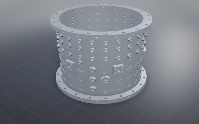
A jet-engine casing, from a reference photo to a solved model
A machined casing rebuilt from one photo, every island fillet blended and the machining check passed.
42/42 root fillets blended VSV mechanism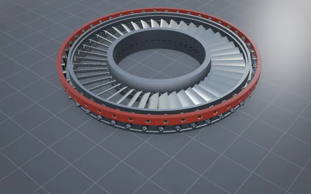
Variable stator vanes, driven from the actuator to every vane
Every compressor vane swings in step through levers, rings and one torque shaft, with every fit measured.
652 parts · 3 vane rows V12 engine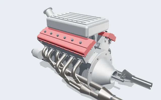
A V12 engine you can run, slice and take apart
Every crank, rod, cam and valve is a real solid, turning in your browser from one dial: the crank angle.
361 parts · 2,850 placements Rear differential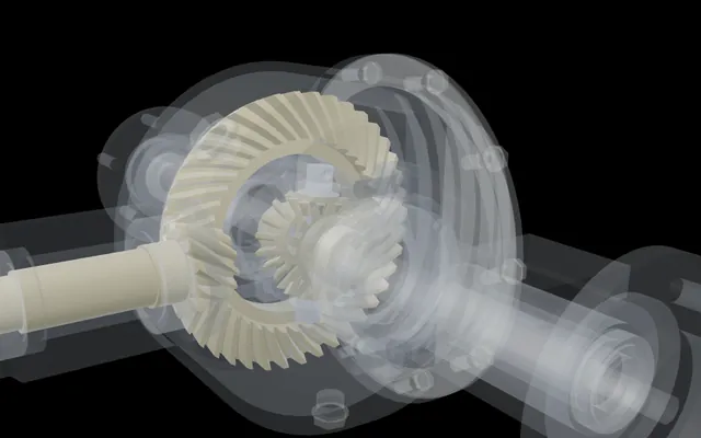
One wheel held, the other turns twice as fast
A complete rear differential with every bolt modelled, driven only by its mates, its feature tree open.
59 parts · 123 matesBuild your own part with NativeCAD
Free for education and makers with a registered key · $200 per seat per year · Kernel SDK for products.