Sheet-metal L-bracket: prompt to drawing sheet
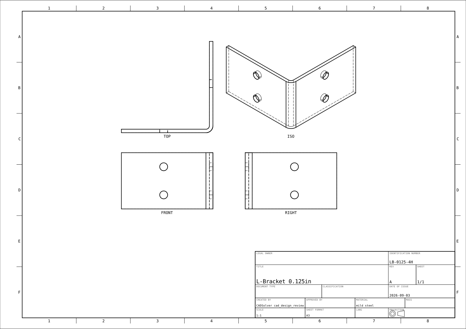
Modeled 2026-09-03 by Claude driving NativeCAD over MCP (v0.7.0 surface). The part, the vendor manufacturability pass that failed it once, the rebuild that cleared it, and the A3 drawing sheet below all came from one sentence plus two follow-ups. Nothing on this page was drawn or typed by hand.
The prompt
“Make an L-shaped sheet metal bracket 0.125 inches thick with 4 mounting holes. Do a manufacturing design pass.”
What got built
0.125 in mild steel, 2 in wide, 3×3 in legs (tangent-to-tangent), one 90° bend, built as a single sheet_fold body with a real cylindrical bend face. Four Ø17/64 in (7.14 mm) clearance holes for 1/4-20 hardware, two per leg, drilled along their own axes with drill_hole — the vertical flange's holes run along −X, not down a nominal top face.
The manufacturing pass caught something
The first body used the textbook 1×-thickness inside radius (3.175 mm). dfm_check was run with a composed route — sheet_metal + scs_laser + scs_bend — so every rule reports the binding limit across laser cutting and press-brake forming, with the vendor pack that sets it. Eighteen rules ran: thirteen passed, four did not apply to a cut-and-bend route, one blocked:
| Rule | Result | Why |
|---|---|---|
| bend_radius_available | FAIL 3.175 mm | The shop tools a fixed list of radii for this material (0.935 … 3.119, 4.994 mm) and offers no custom radius. A part modeled at 3.175 does not come back the shape drawn. |
One rebuild at the shop's 3.119 mm radius with its published K-factor (0.370), four holes re-drilled, and the second pass came back approved: 14 of 14 applicable rules pass, 4 not applicable to a cut-and-bend route.
| Rule | Measured | Limit |
|---|---|---|
| Hole edge to bend centreline | 40.82 mm | ≥ 4.76 mm (half the V-die) |
| Die keep-out band clear | 100 % | ≥ 99.9 % solid |
| Flange reach past the bend | 76.2 mm | ≥ 7.79 mm (half-vee + t) |
| Bend angle | 90° | ≤ 130° |
| Hole diameter | 7.14 mm | ≥ 3.175 mm (1× t) |
| Bend relief | n/a | bend runs out to free edges — none required |
| Bend radius in the shop's set | 3.119 mm | ∈ {0.935 … 4.994} |
The drawing sheet
One more call — a single MCP tool — ran six stages in 183 ms: topology inventory, geometry health, mass properties, DFM, and four standard views with vector hidden-line removal, laid out on an ISO 5457 A3 sheet in ASME Y14.3 third angle at 1:1. Visible edges solid, hidden edges dashed, 5,595 visible segments and 8,693 hidden ones occlusion-tested per sample. Verdict: clean — zero errors, zero warnings, one info (the ISO 7200 title block has no legal owner filled in).
What the checker cannot tell you
The packet is a statement about the checks that ran, not a promise of manufacturability, and the agent said so. Its own notes on top of the automated verdict: the catalog row matched was 0.119 in, not 0.125 in, so confirm the radius on the vendor's bending calculator before ordering; the four outer corners are sharp and would take an R3–R6 corner round for free on a laser; a lone 90° bend in 0.125 in steel flexes under moment load, so a cantilevered use wants a rib or 3/16 in stock; and tolerances, deburr and finish are drawing callouts the model does not carry.
Files
- l-bracket-0125-sheet.svg
- Full packet (HTML)
- Interactive 3D viewer
- l-bracket-0125-flat.dxf
- l-bracket-0125.step
Every number above is kernel-verified from the session transcript. The earlier prompt-to-part demo (2026-09-01, v0.6.0) refused the flat-pattern DXF because the unfolder could not yet develop blanks with holes; two days and one release later it ships the layered DXF above. Rule limits and the bend-radius list come from the vendor's published tables captured 2026-09-02.