Real manufacturing drawings in. STEP out. Checked against the official model.
NIST publishes the machining drawings of real parts together with the 3D models they were made from. NativeCAD rebuilt each part from its drawing alone, then measured the result against NIST's own model. Every drawing produced the same part NIST modelled.
Heat sink matches NIST
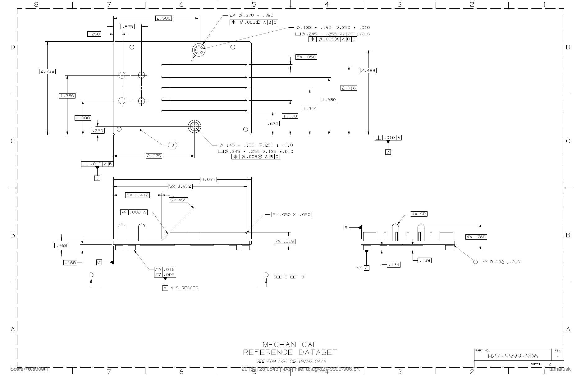
NIST's drawing: Plan, front, right and bottom view D-D over 3 sheets.
Built by NativeCAD from this drawing
Overlay NIST model shows NIST's own model, transparent, over NativeCAD's. Deviation colours NativeCAD's model by its distance to NIST's: blue is on it, red is 0.05 mm or more off. Close-up zooms to fit the part. Drag to orbit, pinch or scroll to zoom.
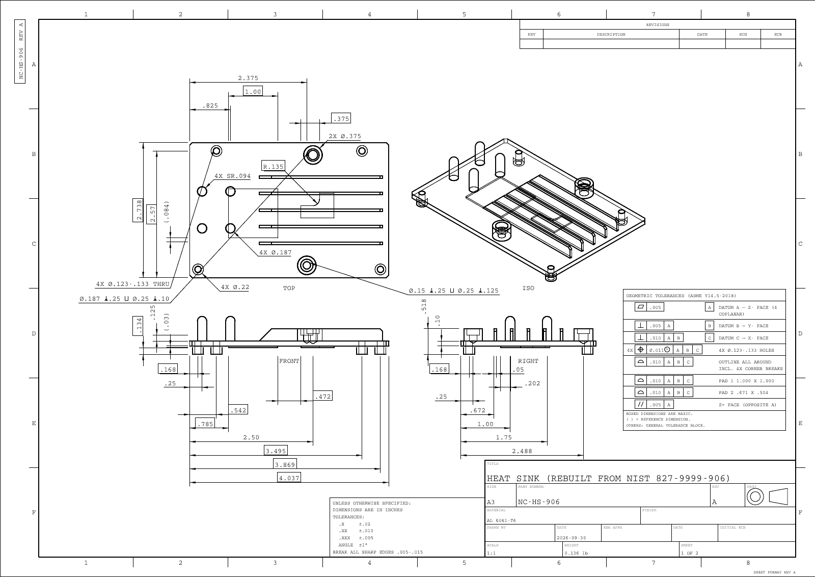
Two inch sheets from NativeCAD's own model: every dimension toleranced, datums A|B|C, hole position sized for a #4 screw (sheet 1); datum and frame schedule, bonus and minimum-wall table and a comparison with NIST's drawing (sheet 2).
Shouldered spacer matches NIST
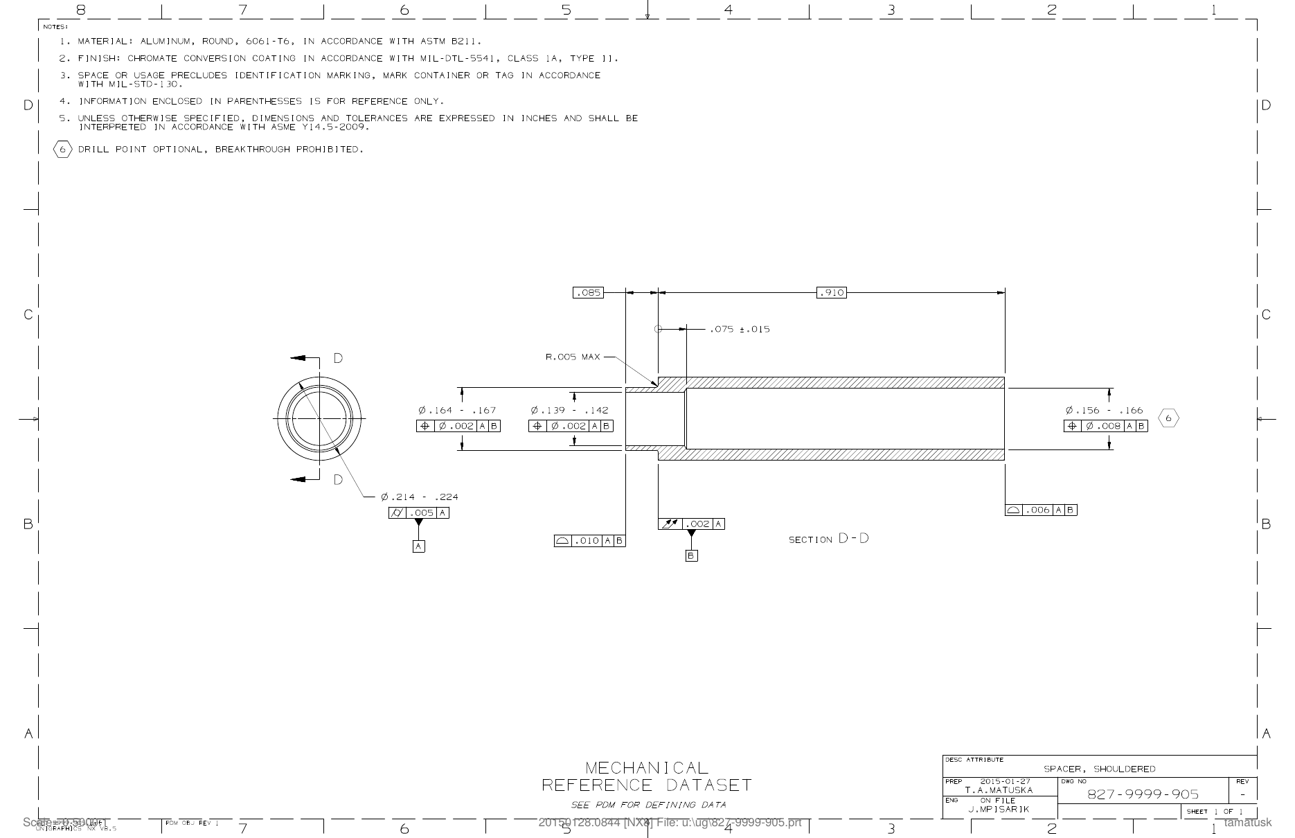
NIST's drawing: End view + full section D-D; every value dimensioned on the sheet.
Built by NativeCAD from this drawing
Overlay NIST model shows NIST's own model, transparent, over NativeCAD's. Deviation colours NativeCAD's model by its distance to NIST's: blue is on it, red is 0.05 mm or more off. Close-up zooms to fit the part. Drag to orbit, pinch or scroll to zoom.
NIST additive-manufacturing test artifact Matches NIST face for face
NIST's standard part for testing 3D printers: pins and holes on both axes, a staircase up and a staircase down, a 1-in-25 ramp, fine pins, holes, ridges and slots down to 0.25 mm, and eight side holes of different shapes. Rebuilt from the paper's drawing alone, then scored against the STEP model NIST publishes.
Built by NativeCAD from this drawing
Overlay NIST model shows NIST's own model, transparent, over NativeCAD's. Deviation colours NativeCAD's model by its distance to NIST's: blue is on it, red is 0.05 mm or more off. Close-up zooms to fit the part. Drag to orbit, pinch or scroll to zoom.
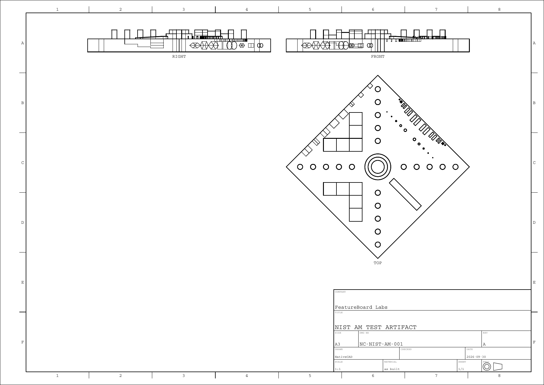
A fresh drawing sheet, drawn by NativeCAD from its own model.
Source drawing — NIST View NIST's drawing (Moylan et al., SFF 2012)
Every dimension on the drawing, checked (148 of 148 within 0.05 mm, 142 exact)
| View | Drawing | Feature | Model | Result |
|---|---|---|---|---|
| B-B | 10 | base thickness (top face) | 10 | ✔ exact |
| B-B | 20 | pin +X 20: axis position | 20 | ✔ exact |
| top | 4 | pin +X 20: ø4 | 4 | ✔ exact |
| B-B | 7 | pin +X 20: height above base | 7 | ✔ exact |
| B-B | 30 | pin +X 30: axis position | 30 | ✔ exact |
| top | 4 | pin +X 30: ø4 | 4 | ✔ exact |
| B-B | 7 | pin +X 30: height above base | 7 | ✔ exact |
| B-B | 40 | pin +X 40: axis position | 40 | ✔ exact |
| top | 4 | pin +X 40: ø4 | 4 | ✔ exact |
| B-B | 7 | pin +X 40: height above base | 7 | ✔ exact |
| B-B | 50 | pin +X 50: axis position | 50 | ✔ exact |
| top | 4 | pin +X 50: ø4 | 4 | ✔ exact |
| B-B | 7 | pin +X 50: height above base | 7 | ✔ exact |
| top | 60 | ø4 THRU +X: axis position | 60 | ✔ exact |
| top | 4 | ø4 THRU +X: diameter | 4 | ✔ exact |
| B-B | 20 | pin -X 20: axis position | 20 | ✔ exact |
| top | 4 | pin -X 20: ø4 | 4 | ✔ exact |
| B-B | 7 | pin -X 20: height above base | 7 | ✔ exact |
| B-B | 30 | pin -X 30: axis position | 30 | ✔ exact |
| top | 4 | pin -X 30: ø4 | 4 | ✔ exact |
| B-B | 7 | pin -X 30: height above base | 7 | ✔ exact |
| B-B | 40 | pin -X 40: axis position | 40 | ✔ exact |
| top | 4 | pin -X 40: ø4 | 4 | ✔ exact |
| B-B | 7 | pin -X 40: height above base | 7 | ✔ exact |
| B-B | 50 | pin -X 50: axis position | 50 | ✔ exact |
| top | 4 | pin -X 50: ø4 | 4 | ✔ exact |
| B-B | 7 | pin -X 50: height above base | 7 | ✔ exact |
| top | 60 | ø4 THRU -X: axis position | 60 | ✔ exact |
| top | 4 | ø4 THRU -X: diameter | 4 | ✔ exact |
| B-B | 20 | pin +Y 20: axis position | 20 | ✔ exact |
| top | 4 | pin +Y 20: ø4 | 4 | ✔ exact |
| B-B | 7 | pin +Y 20: height above base | 7 | ✔ exact |
| B-B | 30 | pin +Y 30: axis position | 30 | ✔ exact |
| top | 4 | pin +Y 30: ø4 | 4 | ✔ exact |
| B-B | 7 | pin +Y 30: height above base | 7 | ✔ exact |
| B-B | 40 | pin +Y 40: axis position | 40 | ✔ exact |
| top | 4 | pin +Y 40: ø4 | 4 | ✔ exact |
| B-B | 7 | pin +Y 40: height above base | 7 | ✔ exact |
| B-B | 50 | pin +Y 50: axis position | 50 | ✔ exact |
| top | 4 | pin +Y 50: ø4 | 4 | ✔ exact |
| B-B | 7 | pin +Y 50: height above base | 7 | ✔ exact |
| top | 60 | ø4 THRU +Y: axis position | 60 | ✔ exact |
| top | 4 | ø4 THRU +Y: diameter | 4 | ✔ exact |
| B-B | 20 | pin -Y 20: axis position | 20 | ✔ exact |
| top | 4 | pin -Y 20: ø4 | 4 | ✔ exact |
| B-B | 7 | pin -Y 20: height above base | 7 | ✔ exact |
| B-B | 30 | pin -Y 30: axis position | 30 | ✔ exact |
| top | 4 | pin -Y 30: ø4 | 4 | ✔ exact |
| B-B | 7 | pin -Y 30: height above base | 7 | ✔ exact |
| B-B | 40 | pin -Y 40: axis position | 40 | ✔ exact |
| top | 4 | pin -Y 40: ø4 | 4 | ✔ exact |
| B-B | 7 | pin -Y 40: height above base | 7 | ✔ exact |
| B-B | 50 | pin -Y 50: axis position | 50 | ✔ exact |
| top | 4 | pin -Y 50: ø4 | 4 | ✔ exact |
| B-B | 7 | pin -Y 50: height above base | 7 | ✔ exact |
| top | 60 | ø4 THRU -Y: axis position | 60 | ✔ exact |
| top | 4 | ø4 THRU -Y: diameter | 4 | ✔ exact |
| B-B | 7 | central tube height above base | 7 | ✔ exact |
| B-B | 4 | central collar height above base | 4 | ✔ exact |
| F-F | 3 | raised step at (-37, 17) | 3 | ✔ exact |
| F-F | 5 | raised step at (-27, 17) | 5 | ✔ exact |
| F-F | 7 | raised step at (-17, 17) | 7 | ✔ exact |
| F-F | 6 | raised step at (-17, 27) | 6 | ✔ exact |
| F-F | 4 | raised step at (-17, 37) | 4 | ✔ exact |
| G-G | 4 | pocket step at (-17, -37) | 4 | ✔ exact |
| G-G | 6 | pocket step at (-17, -27) | 6 | ✔ exact |
| G-G | 7 | pocket step at (-17, -17) | 7 | ✔ exact |
| G-G | 5 | pocket step at (-27, -17) | 5 | ✔ exact |
| G-G | 3 | pocket step at (-37, -17) | 3 | ✔ exact |
| C-C | 1 | ramp: rise over the 25 run | 0.992 | ✔ within 0.05 mm |
| C-C | 1 | ramp: low land height | 1 | ✔ exact |
| C-C | 2.5 | ramp: inner land length | 2.51 | ✔ within 0.05 mm |
| C-C | 25 | ramp: slope run | 24.98 | ✔ within 0.05 mm |
| C-C | 2.5 | ramp: outer land length | 2.51 | ✔ within 0.05 mm |
| D-D | 2 | fine pin ø2 | 2 | ✔ exact |
| D-D | 2 | fine pin ø2: height | 2 | ✔ exact |
| D-D | 2 | fine hole ø2 | 2 | ✔ exact |
| D-D | 2 | fine hole ø2: depth | 2 | ✔ exact |
| D-D | 1.5 | fine pin ø1.5 | 1.5 | ✔ exact |
| D-D | 2 | fine pin ø1.5: height | 2 | ✔ exact |
| D-D | 1.5 | fine hole ø1.5 | 1.5 | ✔ exact |
| D-D | 2 | fine hole ø1.5: depth | 2 | ✔ exact |
| D-D | 1 | fine pin ø1 | 1 | ✔ exact |
| D-D | 2 | fine pin ø1: height | 2 | ✔ exact |
| D-D | 1 | fine hole ø1 | 1 | ✔ exact |
| D-D | 2 | fine hole ø1: depth | 2 | ✔ exact |
| D-D | 0.5 | fine pin ø0.5 | 0.5 | ✔ exact |
| D-D | 2 | fine pin ø0.5: height | 2 | ✔ exact |
| D-D | 0.5 | fine hole ø0.5 | 0.5 | ✔ exact |
| D-D | 2 | fine hole ø0.5: depth | 2 | ✔ exact |
| D-D | 0.25 | fine pin ø0.25 | 0.25 | ✔ exact |
| D-D | 2 | fine pin ø0.25: height | 2 | ✔ exact |
| D-D | 0.25 | fine hole ø0.25 | 0.25 | ✔ exact |
| D-D | 2 | fine hole ø0.25: depth | 2 | ✔ exact |
| E-E | 2 | ridge +2..4: inner edge | 2 | ✔ exact |
| E-E | 4 | ridge +2..4: outer edge | 4 | ✔ exact |
| E-E | 6 | ridge +6..8: inner edge | 6 | ✔ exact |
| E-E | 8 | ridge +6..8: outer edge | 8 | ✔ exact |
| E-E | 11 | ridge +11..12.5: inner edge | 11 | ✔ exact |
| E-E | 12.5 | ridge +11..12.5: outer edge | 12.5 | ✔ exact |
| E-E | 14 | ridge +14..15.5: inner edge | 14 | ✔ exact |
| E-E | 15.5 | ridge +14..15.5: outer edge | 15.5 | ✔ exact |
| E-E | 17.5 | ridge +17.5..18.5: inner edge | 17.5 | ✔ exact |
| E-E | 18.5 | ridge +17.5..18.5: outer edge | 18.5 | ✔ exact |
| E-E | 19.5 | ridge +19.5..20.5: inner edge | 19.5 | ✔ exact |
| E-E | 20.5 | ridge +19.5..20.5: outer edge | 20.5 | ✔ exact |
| E-E | 22 | ridge +22..22.5: inner edge | 22 | ✔ exact |
| E-E | 22.5 | ridge +22..22.5: outer edge | 22.5 | ✔ exact |
| E-E | 23 | ridge +23..23.5: inner edge | 23 | ✔ exact |
| E-E | 23.5 | ridge +23..23.5: outer edge | 23.5 | ✔ exact |
| E-E | 24.5 | ridge +24.5..24.75: inner edge | 24.5 | ✔ exact |
| E-E | 24.75 | ridge +24.5..24.75: outer edge | 24.75 | ✔ exact |
| E-E | 25 | ridge +25..25.25: inner edge | 25 | ✔ exact |
| E-E | 25.25 | ridge +25..25.25: outer edge | 25.25 | ✔ exact |
| E-E | 2 | slot -2..4: inner edge | 2 | ✔ exact |
| E-E | 4 | slot -2..4: outer edge | 4 | ✔ exact |
| E-E | 6 | slot -6..8: inner edge | 6 | ✔ exact |
| E-E | 8 | slot -6..8: outer edge | 8 | ✔ exact |
| E-E | 11 | slot -11..12.5: inner edge | 11 | ✔ exact |
| E-E | 12.5 | slot -11..12.5: outer edge | 12.5 | ✔ exact |
| E-E | 14 | slot -14..15.5: inner edge | 14 | ✔ exact |
| E-E | 15.5 | slot -14..15.5: outer edge | 15.5 | ✔ exact |
| E-E | 17.5 | slot -17.5..18.5: inner edge | 17.5 | ✔ exact |
| E-E | 18.5 | slot -17.5..18.5: outer edge | 18.5 | ✔ exact |
| E-E | 19.5 | slot -19.5..20.5: inner edge | 19.5 | ✔ exact |
| E-E | 20.5 | slot -19.5..20.5: outer edge | 20.5 | ✔ exact |
| E-E | 22 | slot -22..22.5: inner edge | 22 | ✔ exact |
| E-E | 22.5 | slot -22..22.5: outer edge | 22.5 | ✔ exact |
| E-E | 23 | slot -23..23.5: inner edge | 23 | ✔ exact |
| E-E | 23.5 | slot -23..23.5: outer edge | 23.5 | ✔ exact |
| E-E | 24.5 | slot -24.5..24.75: inner edge | 24.5 | ✔ exact |
| E-E | 24.75 | slot -24.5..24.75: outer edge | 24.75 | ✔ exact |
| E-E | 25 | slot -25..25.25: inner edge | 25 | ✔ exact |
| E-E | 25.25 | slot -25..25.25: outer edge | 25.25 | ✔ exact |
| E-E | 2 | ridge height | 2 | ✔ exact |
| E-E | 2 | slot depth | 2 | ✔ exact |
| A-A | 3 | lateral ø3 | 3 | ✔ exact |
| A-A | 3 | lateral ø3: depth | 3 | ✔ exact |
| A-A | 6 | lateral ø6 | 6 | ✔ exact |
| A-A | 5 | lateral ø6: depth | 5 | ✔ exact |
| A-A | 3 | lateral square 3: width | 3 | ✔ exact |
| A-A | 3 | lateral square 3: height | 3 | ✔ exact |
| A-A | 3 | lateral diamond 3: across corners | 3 | ✔ exact |
| A-A | 6 | lateral square 6: width | 6 | ✔ exact |
| A-A | 6 | lateral square 6: height | 6 | ✔ exact |
| A-A | 6 | lateral diamond 6: across corners | 6 | ✔ exact |
| A-A | 60 | lateral 60° rhombus (vertical): tip angle | 59.999 | ✔ within 0.05° |
| A-A | 60 | lateral 60° rhombus (horizontal): tip angle | 60.001 | ✔ within 0.05° |
Every callout on NIST's drawing, down to the 0.25 mm pins and slots, is within 0.05 mm of NativeCAD's model (0.05° for angles): 142 match the drawing's value exactly, and the other 6 are marked within tolerance in the table.
Manufacturer drawings to full assemblies
Product drawings from the maker's own datasheet, rebuilt as native STEP assemblies with every dimension on the drawing checked against the model.
Raspberry Pi Global Shutter Camera 30 of 31 dimensions exact
A 10-part camera assembly from the manufacturer's mechanical drawing: CS-mount lens tube, back-focus ring and clamps, lens holder, tripod mount, board, sensor and cover, each part where the drawing puts it.
Built by NativeCAD from this drawing
NativeCAD's assembly. Drag to orbit, scroll to zoom; the clip control cuts it open.
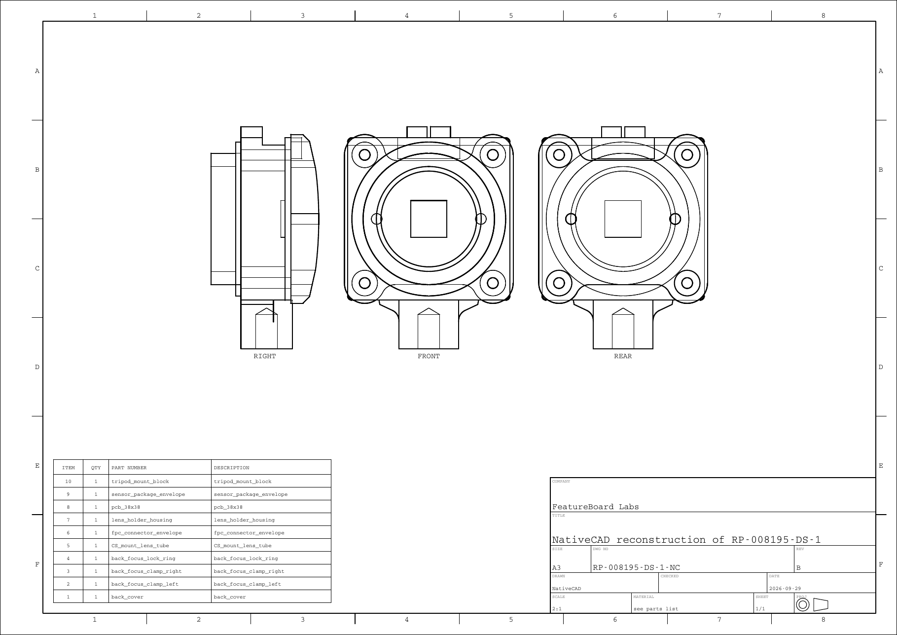
A fresh drawing sheet, drawn by NativeCAD from its own model.
Source drawing — Raspberry Pi Ltd View Raspberry Pi Ltd's drawing (PDF)
Every dimension on the drawing, checked (30 of 31 exact)
| View | Drawing | Feature | Model | Result |
|---|---|---|---|---|
| side | 10.35 | housing front face -> PCB front face | 10.35 | ✔ exact |
| side | 5.02 | back-focus clamp depth | 5.02 | ✔ exact |
| side | 1.2 | back-focus lock ring thickness | 1.2 | ✔ exact |
| side | 5.8 | CS-mount lens tube length | 5.8 | ✔ exact |
| side | 1.4 | PCB thickness | 1.4 | ✔ exact |
| side | 6.49 | back cover thickness at crown (PCB back -> cover back) | 6.49 | ✔ exact |
| side | 12.04 | tripod block depth from housing front | 12.04 | ✔ exact |
| side | 7.62 | tripod flank depth from housing front | 7.62 | ✔ exact |
| side | 25.07 | overall depth, lens tube front -> cover back | 25.24 | source mismatch |
| side | 39.5 | back cover height | 39.5 | ✔ exact |
| front | 4 | corner hole centre from board edge | 4.0 | ✔ exact |
| front | 10.16 | back-focus clamp width | 10.16 | ✔ exact |
| front | 0.8 | clamp slot width | 0.8 | ✔ exact |
| front | ø2.5 | corner mounting holes (M2.5 clearance), 30 mm pitch | 2.5 | ✔ exact |
| front | ø22.4 | clear aperture bore | 22.4 | ✔ exact |
| front | ø30.75 | CS-mount tube OD | 30.75 | ✔ exact |
| front | ø36 | back-focus lock ring OD | 36.0 | ✔ exact |
| front | 8.5 | sensor window width | 8.5 | ✔ exact |
| front | 38 | board/housing height | 38.0 | ✔ exact |
| front | 38 | board/housing width | 38.0 | ✔ exact |
| front | 13.97 | tripod block width | 13.97 | ✔ exact |
| back | 39.5 | back cover width | 39.5 | ✔ exact |
| back | 39.5 | back cover height | 39.5 | ✔ exact |
| back | 7.56 | cover screw hole centre from side edge | 7.56 | ✔ exact |
| back | 4.75 | corner lobe centre from edge | 4.75 | ✔ exact |
| back | 19.75 | cover screw hole centre from top edge | 19.75 | ✔ exact |
| back | 30 | corner lobe / hole pitch | 30.0 | ✔ exact |
| back | 24.38 | cover screw hole spacing (2 x 12.19) | 24.38 | ✔ exact |
| back | ø5.99 | corner lobe through-holes | 5.99 | ✔ exact |
| back | ø2.5 | cover screw holes | 2.5 | ✔ exact |
| back | R4.75 | corner lobe radius | 4.75 | ✔ exact |
The one miss is in the source: its stacked depths (5.8 + 1.2 + 10.35 + 1.4 + 6.49) add up to 25.24 mm, while its overall callout says 25.07. The model keeps the feature dimensions.
Raspberry Pi High Quality Camera (CS mount) 20 of 21 dimensions exact
The same lens-mount family, from its own drawing: the front half is dimensioned identically to the Global Shutter Camera, so those nine parts carry straight over, and the board-mounted ribbon connector is built from the new drawing.
Built by NativeCAD from this drawing
NativeCAD's assembly. Drag to orbit, scroll to zoom; the clip control cuts it open.
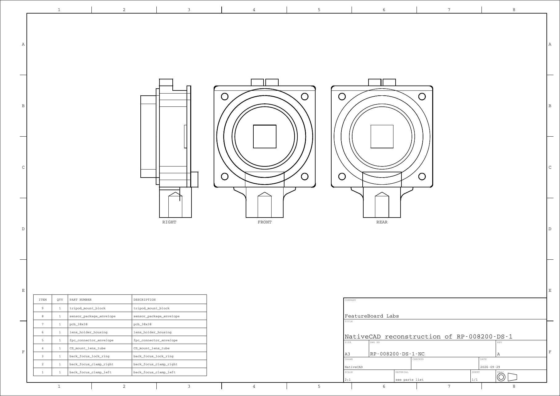
A fresh drawing sheet, drawn by NativeCAD from its own model.
Source drawing — Raspberry Pi Ltd View Raspberry Pi Ltd's drawing (PDF)
Every dimension on the drawing, checked (20 of 21 exact)
| View | Drawing | Feature | Model | Result |
|---|---|---|---|---|
| side | 10.35 | housing front face -> PCB front face | 10.35 | ✔ exact |
| side | 5.02 | back-focus clamp depth | 5.02 | ✔ exact |
| side | 1.2 | back-focus lock ring thickness | 1.2 | ✔ exact |
| side | 5.8 | CS-mount lens tube length | 5.8 | ✔ exact |
| side | 1.4 | PCB thickness | 1.4 | ✔ exact |
| side | 5.71 | ribbon connector height (flush with the board edge) | 5.71 | ✔ exact |
| side | 2.75 | ribbon connector depth behind the PCB | 2.75 | ✔ exact |
| side | 7.62 | tripod flank depth from housing front | 7.62 | ✔ exact |
| side | 12.04 | tripod block depth from housing front | 12.04 | ✔ exact |
| side | 18.58 | overall depth, lens tube front -> PCB back | 18.75 | source mismatch |
| front | 4 | corner hole centre from board edge | 4 | ✔ exact |
| front | 10.16 | back-focus clamp width | 10.16 | ✔ exact |
| front | 0.8 | clamp slot width | 0.8 | ✔ exact |
| front | ø2.5 | corner mounting holes, 30 mm pitch | 2.5 | ✔ exact |
| front | ø22.4 | clear aperture bore | 22.4 | ✔ exact |
| front | ø30.75 | CS-mount tube OD | 30.75 | ✔ exact |
| front | ø36 | back-focus lock ring OD | 36 | ✔ exact |
| front | 8.5 | sensor window width | 8.5 | ✔ exact |
| front | 38 | board/housing height | 38 | ✔ exact |
| front | 38 | board/housing width | 38 | ✔ exact |
| front | 13.97 | tripod block width | 13.97 | ✔ exact |
The one miss is in the source again: 5.8 + 1.2 + 10.35 + 1.4 add up to 18.75 mm, while the overall callout says 18.58. It is the same 0.17 mm gap as the Global Shutter drawing, so the model keeps the feature dimensions.
Raspberry Pi 5 25 of 25 dimensions exact
A full board from a one-page drawing: every port, header and package placed on the 85 x 56 board where the drawing puts it, ready for enclosure and bracket design.
Built by NativeCAD from this drawing
NativeCAD's assembly. Drag to orbit, scroll to zoom; the clip control cuts it open.
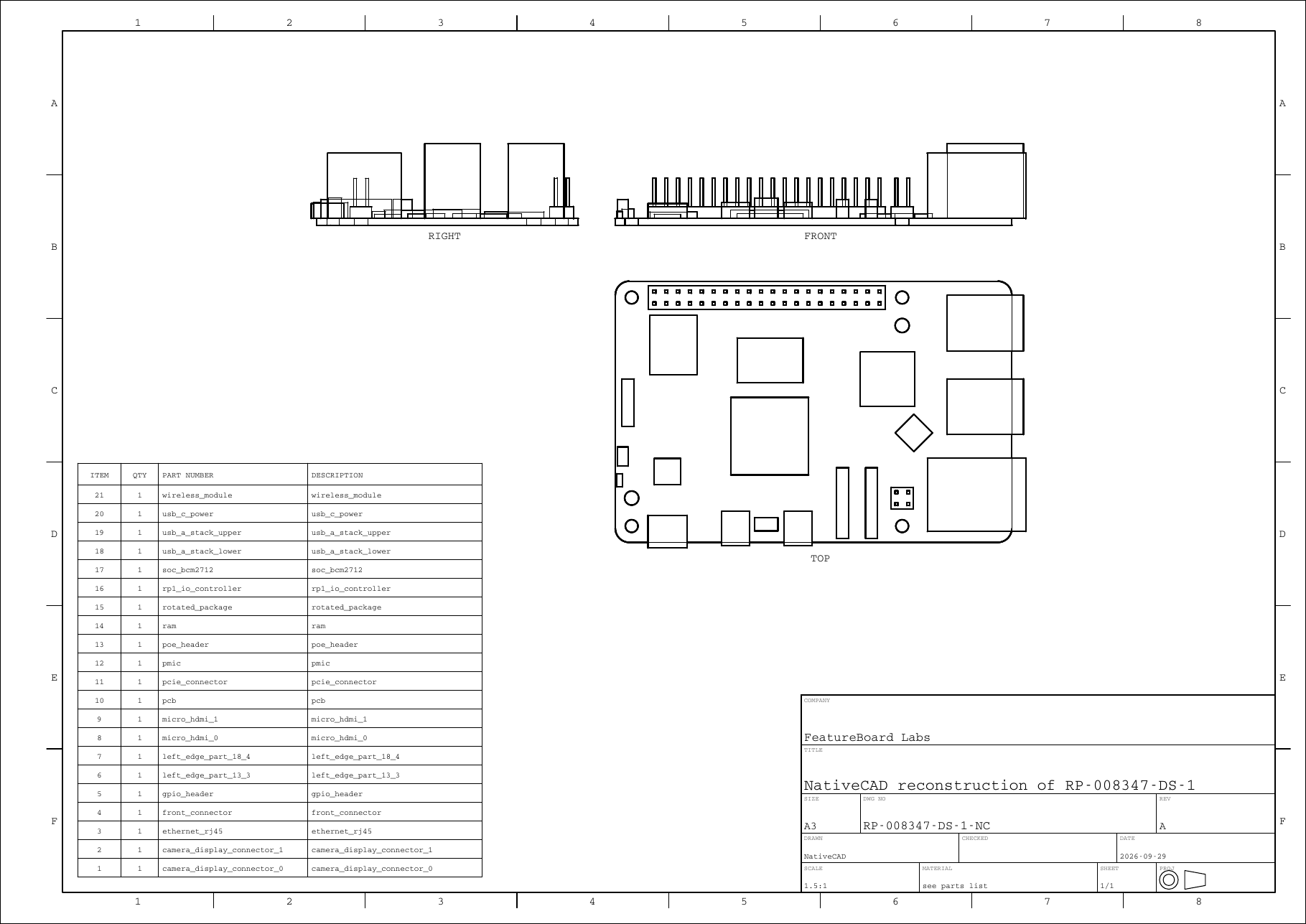
A fresh drawing sheet, drawn by NativeCAD from its own model.
Source drawing — Raspberry Pi Ltd View Raspberry Pi Ltd's drawing (PDF)
Every dimension on the drawing, checked (25 of 25 exact)
| View | Drawing | Feature | Model | Result |
|---|---|---|---|---|
| top | 85 | board length | 85 | ✔ exact |
| top | 56 | board width | 56 | ✔ exact |
| top | 58 | mounting-hole pitch along the board | 58 | ✔ exact |
| top | 49 | mounting-hole pitch across the board | 49 | ✔ exact |
| top | 3.5 | mounting-hole centre from the board edge | 3.5 | ✔ exact |
| top | ø2.7 | mounting holes | 2.7 | ✔ exact |
| top | ø3 | cooler holes | 3 | ✔ exact |
| top | 6 | lower cooler hole above the lower-left mounting hole | 6 | ✔ exact |
| top | 6 | upper cooler hole below the upper-right mounting hole | 6 | ✔ exact |
| top | 29 | GPIO header centre from the left mounting hole | 29 | ✔ exact |
| top | 11.2 | USB-C centre from the board edge | 11.2 | ✔ exact |
| top | 25.8 | micro-HDMI 0 centre | 25.8 | ✔ exact |
| top | 39.2 | micro-HDMI 1 centre | 39.2 | ✔ exact |
| top | 18.4 | left-edge part centre | 18.4 | ✔ exact |
| top | 13.3 | left-edge part centre | 13.3 | ✔ exact |
| top | 10.2 | Ethernet centre | 10.2 | ✔ exact |
| top | 29.1 | lower USB-A stack centre | 29.1 | ✔ exact |
| top | 47 | upper USB-A stack centre | 47 | ✔ exact |
| top | 3 | Ethernet proud of the board edge | 3 | ✔ exact |
| side | 0.45 | left-edge part in from the board edge | 0.45 | ✔ exact |
| side | 4.1 | left-edge part height | 4.1 | ✔ exact |
| side | 3.2 | USB-C height | 3.2 | ✔ exact |
| side | 3.4 | micro-HDMI height | 3.4 | ✔ exact |
| side | 4.4 | front connector height | 4.4 | ✔ exact |
| side | 4.1 | camera / display connector height | 4.1 | ✔ exact |
Every port, header and mounting hole sits where Raspberry Pi's drawing puts it.
Drawing in, STEP out
Hand NativeCAD a manufacturing drawing, get back a STEP model that matches the part. NativeCAD then draws its own shop-ready sheet of the rebuilt part: see the heat sink drawing (PDF).
Have drawings you need as 3D? Get a free key or see DXF & PDF drawing import.
More demos
All demos →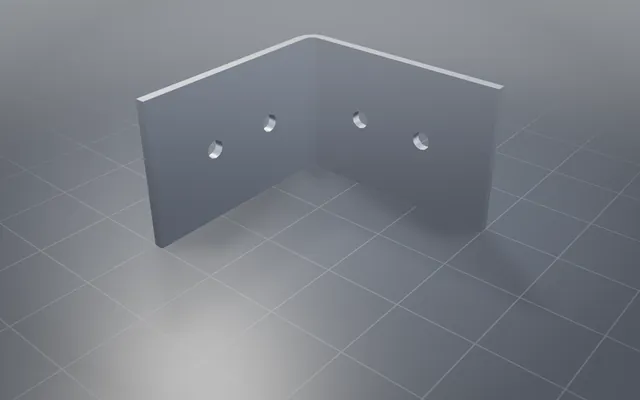
Text to CAD, scored on real part requests
Recipes for plain-English part requests, replayed with no model in the loop, scored on a checked solid.
94.2% of 86 replays pass L-bracket demoFrom one sentence to a checked bracket and its STEP file
Type what you need and an AI agent builds the bracket, checks it for manufacture and hands you the STEP file.
L-bracket drawingThe same bracket, as a dimensioned shop drawing
The bracket arrives with a dimensioned drawing sheet, ready to send with the STEP file.
V12 engine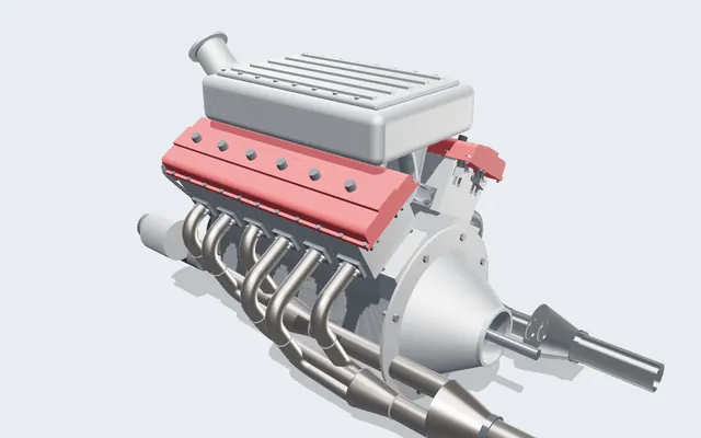
A V12 engine you can run, slice and take apart
Every crank, rod, cam and valve is a real solid, turning in your browser from one dial: the crank angle.
361 parts · 2,850 placementsBuild your own part with NativeCAD
Free for education and makers with a registered key · $200 per seat per year · Kernel SDK for products.