A jet engine, solved: compressible CFD, combustion chemistry and a full start-up in one loop.
NativeCAD puts a fast engineering model at the centre of a design and wires real solvers around it. SU2 solves the compressible flow through the compressor and the exhaust nozzle, Cantera burns the fuel zone by zone, and the fast model runs the whole engine from starter to full power with their results built in. Every number traces back to the run that made it.
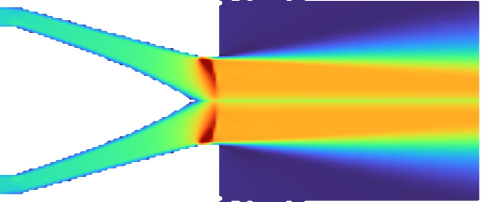
The built exhaust nozzle, solved: exit Mach 0.868 and 298.1 N of thrust against the 300 N target. How ↓calibrate: a solver measures a correction and the fast model is re-run with itcheck: a solver re-computes a result the fast model already gavedashed: done on other parts, next on this engine
0.86 → 0.965nozzle flow coefficient: what CFD measured on the first nozzle, then on the reshaped one
0.11 %compressor CFD against the fast model, mass flow at the design pressure ratio
1,098.5 Kcombustor exit from the chemistry solver, against a 1,100 K target
13.6 sfrom starter on to idle, simulated with the calibrated model
Compressible CFD: the exhaust nozzle
The nozzle is where the thrust comes from, so we solve it properly: SU2 8.5.0, compressible Reynolds-averaged Navier–Stokes with the Spalart–Allmaras turbulence model, axisymmetric, from the turbine exit out into the exhaust plume on 73,000 cells. The inlet is the cycle's own turbine-exit state, and the walls are the nozzle and tail cone the parts are built to.
0.598 kg/smass flow, cycle 0.594 kg/s
0.868exit Mach, area-averaged (0.665 on the axis)
298.1 Nthrust, against a 300 N target
0.982total pressure kept through the nozzle
The field at the top of this page is that solution. Gas arrives as an annular jet along the outer wall, closes in behind the tail cone and accelerates through the 15° cone to about 500 m/s at the exit. It leaves the lip still converging, and that is where the flow deficit sits rather than in a pressure loss: the nozzle keeps 98.2 % of its total pressure. A fast model cannot see that; the CFD can, and it is what reshaped this nozzle (step 4 below).
Compressible CFD: transonic flow on the compressor blades
SU2 also solves the compressor: one passage of the 12-blade impeller in the rotating frame, 47,040 cells, at 6 back pressures. That traces the impeller's speed line from a pressure ratio of 2.95 to 4.30. At the design pressure ratio of 3.5 the CFD passes 0.584 kg/s against the cycle's 0.583. On the blades the flow goes supersonic: the suction-side Mach number peaks at 1.19 at mid-span and 1.39 near the tip.
Speed line and efficiency from the 6 back pressures. Blade-surface Mach from the wall pressure on the suction side, at the back pressure nearest the design pressure ratio. The passage is meshed without a tip gap, so the efficiency reads on the high side.
Combustion chemistry, zone by zone
Cantera 3.2.0 models the combustor as a network of reactors with the GRI-Mech 3.0 mechanism and a jet-fuel surrogate: two stirred reactors where the flame sits, then two flow reactors where the rest of the air mixes in. Each strip below is the gas leaving one zone.
452 Kair incompressor exit
2,258 Kzone 1 · PSR+27 % air
2,337 Kzone 2 · PSRno added air
2,096 Kzone 3 · PFR+7 % air
1,099 Kzone 4 · PFR+67 % air
99.8 %combustion efficiency
2,337 Khottest zone, cooled to the turbine's limit by the dilution air
219 ppmCO at design, dry, 15 % O2
12 of 12throttle points where the network and the blowout screen agree
Will it stay lit?
Along the throttle line a lean-blowout screen and the reactor network both rate the flame. The sized liner stays lit all the way down to 45 % throttle, with a margin of 0.31 on the screen and 96 % in the network. As a control, a deliberately half-size liner goes through the same screen and blows out below 60 % throttle: the screen catches a bad design.
LBO margin is 1 minus the ratio of blowout loading to actual loading, one scale for every line: zero is blowout, above zero is stable.
How the solvers feed each other
Our worked example is a small jet engine: 300 N of thrust, a compressor turning at 64,213 rpm and a turbine inlet at 1,100 K. Every part is a real solid in NativeCAD. The fast model does the design in a blink; the solvers calibrate it (measure a correction and feed it back as a plain number) or check it (re-compute a result it already gave). When a correction changes the shape, the loop runs again.
The fast model sizes the engine
The engine cycle works out the air flow (0.583 kg/s), the temperatures and pressures at every station, and the size of every passage. NativeCAD builds the parts from those sizes.
SU2 checks the compressor
Quick blade-row estimates give the compressor and turbine maps. Compressible CFD on the impeller checks them: 6 points along its speed line, and at the design pressure ratio the simulated air flow lands 0.11 % from the model (the limit was 5 %).
Cantera calibrates the burner, then checks it
The chemistry solver worked out how hot jet fuel burns over 3,321 combinations of inlet temperature, pressure and fuel-to-air ratio. That table now sets how much fuel the fast model burns. Then a separate chemistry run models the combustor itself as 4 zones and checks the result: 1,098.5 K at the exit against the 1,100 K target, 0.13 % off, inside the 2 % limit.
SU2 calibrates the nozzle
The first SU2 run on the first nozzle found it let through less gas than the model assumed: a flow coefficient (Cd) of 0.86 where the model had 1.00, so 262 N of thrust instead of 300 and 12.8 % too little gas.
So we reshaped it, with a 15° cone and a short straight lip at the exit, and sized the opening for a Cd of 0.97: 2,916 mm² instead of 2,829. The re-run measured 0.965 and 298.1 N, 0.6 % off the target. Each run took 34 and 64 minutes, which is exactly why the solver sits outside the fast model.
The start-up, with everything calibrated
With the burner and nozzle calibrated, the fast model plays a full start: starter, light-off at 2.9 s, idle at 13.6 s, full power 11.5 s later. The turbine never sees more than 1,100 K and the compressor keeps at least 26 % margin from stall. The energy books balance to 0.065 %.
Watch it start
The real engine, cut open, running the start-up above. Gas is coloured by temperature, the flame by the chemistry solver's zones, the jet by the airflow simulation. Turn and move the cut, orbit and zoom.
Loading the start-up run…
Simulated from the cycle and CFD results
0.0 s
View settings
–rpm
–exhaust gas temperature
–thrust
–fuel flow
▬ rpm▬ EGT · particles coloured by gas temperature, 300 K2,400 K
Every number can be traced
A record for every correction
Each correction stores its value, its unit, the solver and version, the run, the inputs and a fingerprint of the result file. Replay the record and the whole loop re-runs without a single solver, to the same answer.
Pass marks set before the run
Every solver check has its acceptance limit fixed before the first run, and limits never move to fit a result.
Nobody grades their own work
The code that grades a result may not share code with the code that made it, and a test enforces that.
Limits today: the cad_couple tool is in the NativeCAD release and runs this loop, with Cantera and SU2 as calibrators, a run record with a content hash, and a replay that needs no solver. The coupling covers scalar correction factors only. Blade-row CFD and conjugate heat transfer (gas and metal temperatures solved together) are not part of it: the compressor and turbine maps are meanline correlations, and the metal temperature is not solved with the gas.
Bring us a problem
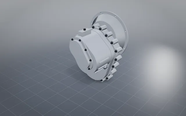
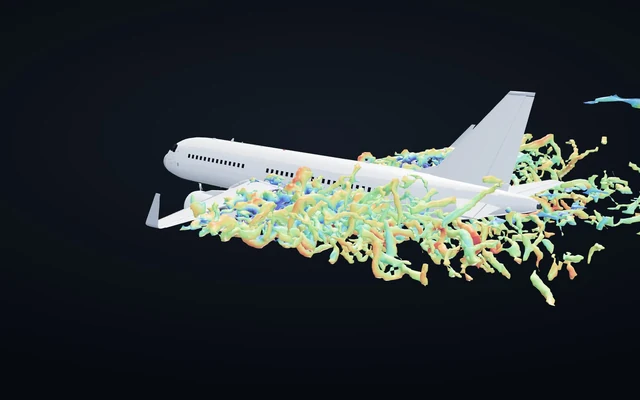
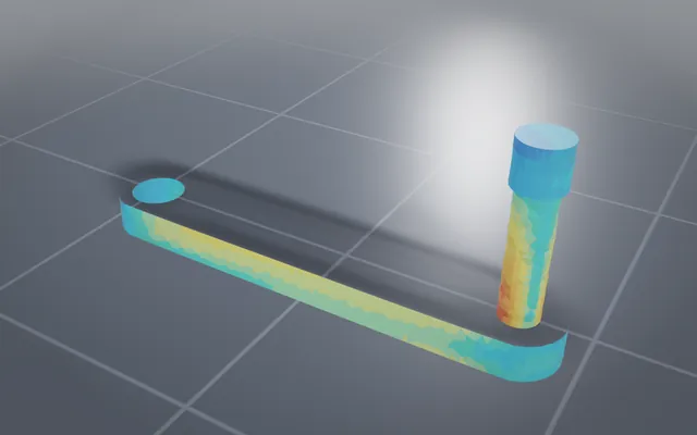
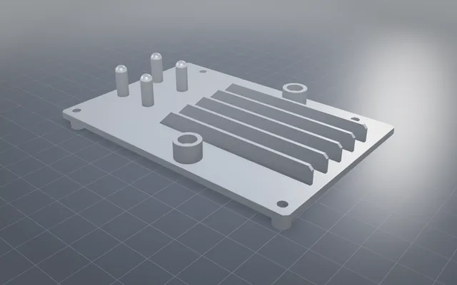
The pattern is not about jet engines. A fast model of your product in the middle, the right solver for each question around it, and a record behind every number. We have built pieces of it for all of these:
Pumps and turbopumps, pressure vessels, rocket engines, robot arms: if it can be modelled fast and checked by a solver, we can wire the loop. Tell us what you want built.
Tell us what you want built
NativeCAD runs inside your AI assistant. Bring a part, a product or a problem, and we will build the loop around it.
 SU2 · compressible RANS · Mach number