NativeCAD MCP server · design loops
The DFM design loop closes its own findings
Eight prompts, two per process — machining, injection moulding, sheet metal, additive — whose first build breaks a named design-for-manufacture rule on purpose: a thin wall, no draft, an unrelieved internal corner, an undersized pin. The loop runs cad_dfm_check, takes the remedy its finding names — a face to push out, edges to fillet, walls to draft — and sends it straight back to the kernel. No fillet radius or draft angle on this page was chosen by a person or by the loop: every number below is what the kernel measured before and after its own fix, and every picture is the kernel's own render or section of the body it measured.
 Machining (CNC mill)
 Machining (CNC mill)
 Injection moulding
 Injection moulding
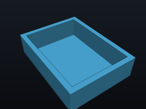 Sheet metal
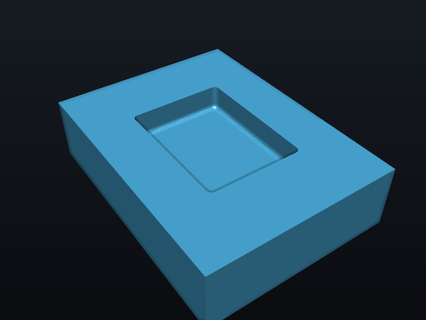 Sheet metal
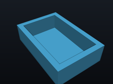 Additive (FDM)
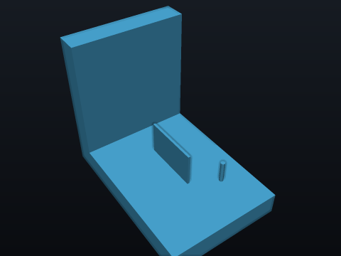 Additive (Bambu X1 Carbon)
The eight parts as the loop left them, each one passing its process's rule pack. Pick one to see how it got there.
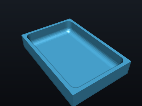
Machining (CNC mill)
Machine a 60 x 40 x 10 mm aluminium tray with a pocket leaving a 0.5 mm floor.
PASS · 3 iterationsThin wall and unrelieved internal corner — the pocket floor is under the machining pack's hard wall floor, and its square corners are sharper than any 6 mm end mill can cut. The second rule was not deliberately dialled in — a square pocket cut with no corner relief always leaves sharp internal corners — but it is real and the loop closes it exactly like the one it was written for.
Rule(s) under test: min_wall_thickness, min_internal_corner_radius
| iter | op applied | rule — measured vs limit | gate |
|---|---|---|---|
| 0 | (first build) | min wall thickness: 0.5 mm vs 0.8 mm FAIL min internal corner radius: 0 mm vs 3.6 mm FAIL | 2 blocking |
| 1 | cad_move_face | min wall thickness: 0.8 mm vs 0.8 mm PASS min internal corner radius: 0 mm vs 3.6 mm FAIL | 1 blocking |
| 2 | cad_fillet_edges | min wall thickness: 0.8 mm vs 0.8 mm PASS min internal corner radius: 3.6 mm vs 3.6 mm PASS | approved |
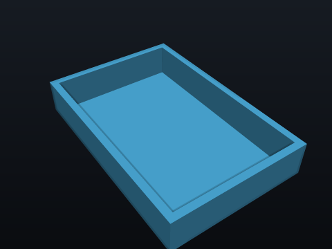
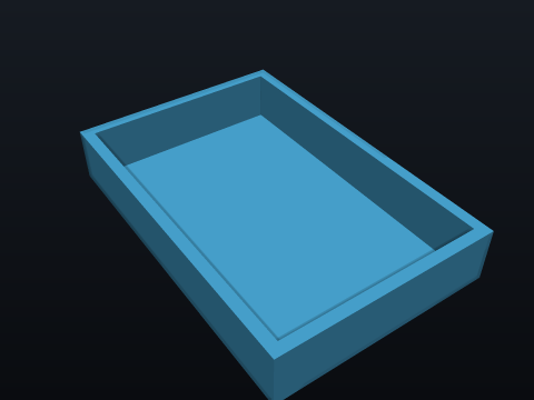
cad_move_facecad_fillet_edges passesmin wall thickness 0.5 → 0.8 mm (limit 0.8 mm) · min internal corner radius 0 → 3.6 mm (limit 3.6 mm)
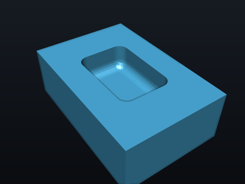
Mill a 60 x 40 x 20 mm block with a square-cornered 30 x 20 x 12 mm pocket — no corner relief for the cutter.
PASS · 2 iterationsUnrelieved internal corner — the pocket's square corners are sharper than any 6 mm end mill can cut.
Rule(s) under test: min_internal_corner_radius
| iter | op applied | rule — measured vs limit | gate |
|---|---|---|---|
| 0 | (first build) | min internal corner radius: 0 mm vs 3.6 mm FAIL | 1 blocking |
| 1 | cad_fillet_edges | min internal corner radius: 3.6 mm vs 3.6 mm PASS | approved |
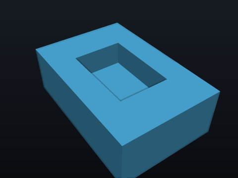
cad_fillet_edges passesmin internal corner radius 0 → 3.6 mm (limit 3.6 mm)
Injection moulding
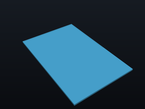
Injection-mould a 60 x 40 x 0.8 mm plate, vertical walls, no draft.
PASS · 3 iterationsThin wall and no draft — the 0.8 mm plate is under the 1 mm wall floor and dead vertical against the pull.
Rule(s) under test: min_wall_thickness, min_draft_angle
| iter | op applied | rule — measured vs limit | gate |
|---|---|---|---|
| 0 | (first build) | min wall thickness: 0.8 mm vs 1 mm FAIL min draft angle: 0 deg vs 1 deg FAIL | 2 blocking |
| 1 | cad_move_face | min wall thickness: 1 mm vs 1 mm PASS min draft angle: 0 deg vs 1 deg FAIL | 1 blocking |
| 2 | cad_draft | min wall thickness: 1 mm vs 1 mm PASS min draft angle: 1 deg vs 1 deg PASS | approved |

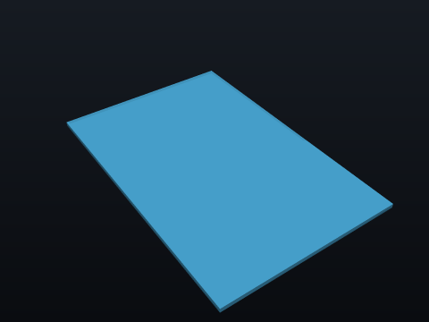
cad_move_facecad_draft passesmin wall thickness 0.8 → 1 mm (limit 1 mm) · min draft angle 0 → 1 deg (limit 1 deg)
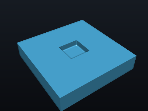
Injection-mould a 40 x 40 x 8 mm plate with a shallow square 10 x 10 x 3 mm pocket, no draft, no corner relief.
PASS · 3 iterationsNo draft and unrelieved internal corner — every wall is dead vertical and the pocket's corners are sharp.
Rule(s) under test: min_internal_corner_radius, min_draft_angle
| iter | op applied | rule — measured vs limit | gate |
|---|---|---|---|
| 0 | (first build) | min internal corner radius: 0 mm vs 0.5 mm FAIL min draft angle: 0 deg vs 1 deg FAIL | 1 blocking |
| 1 | cad_fillet_edges | min internal corner radius: 0.5 mm vs 0.5 mm PASS min draft angle: 0 deg vs 1 deg FAIL | 1 blocking |
| 2 | cad_draft | min internal corner radius: 0.5 mm vs 0.5 mm PASS min draft angle: 1 deg vs 1 deg PASS | approved |
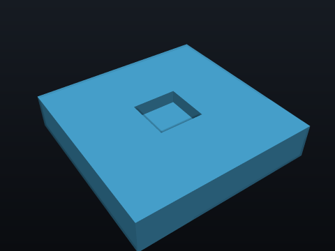
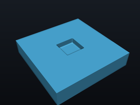
cad_fillet_edgescad_draft passesmin internal corner radius 0 → 0.5 mm (limit 0.5 mm) · min draft angle 0 → 1 deg (limit 1 deg)
Sheet metal
Laser-cut and form a 40 x 30 x 10 mm sheet-metal tray with a pocket leaving a 0.3 mm floor.
PASS · 2 iterationsThin wall — under the sheet-metal pack's sanity floor on the sheet itself.
Rule(s) under test: min_wall_thickness
Also trips min_internal_corner_radius (not under test): severity warning on the sheet_metal pack: the pocket has no corner relief; it fails the rule, not the gate, so the loop closes on the named rule alone
| iter | op applied | rule — measured vs limit | gate |
|---|---|---|---|
| 0 | (first build) | min wall thickness: 0.3 mm vs 0.5 mm FAIL | approved |
| 1 | cad_move_face | min wall thickness: 0.5 mm vs 0.5 mm PASS | approved |
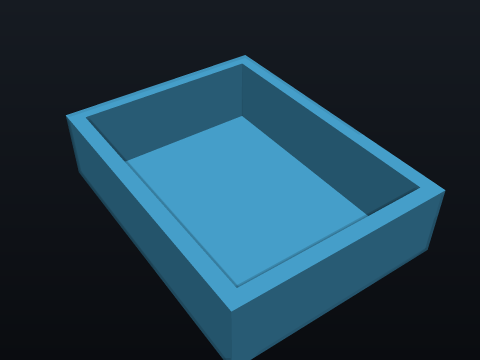
cad_move_face passesmin wall thickness 0.3 → 0.5 mm (limit 0.5 mm)
Laser-cut a 40 x 30 x 10 mm sheet-metal block with a square 20 x 15 x 5 mm pocket — no corner relief for the cutting head.
PASS · 2 iterationsUnrelieved internal corner — the pocket's square corners are sharper than the sheet-metal pack's cut-corner floor.
Rule(s) under test: min_internal_corner_radius
| iter | op applied | rule — measured vs limit | gate |
|---|---|---|---|
| 0 | (first build) | min internal corner radius: 0 mm vs 0.75 mm FAIL | approved |
| 1 | cad_fillet_edges | min internal corner radius: 0.75 mm vs 0.75 mm PASS | approved |
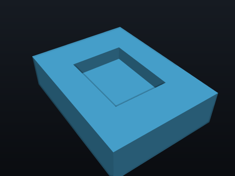
cad_fillet_edges passesmin internal corner radius 0 → 0.75 mm (limit 0.75 mm)
Additive (FDM)
3D-print a 30 x 20 x 8 mm FDM tray with a pocket leaving a 0.4 mm floor.
PASS · 2 iterationsThin wall — under two perimeters of the FDM pack's extrusion width, so it prints as a gap.
Rule(s) under test: min_wall_thickness
| iter | op applied | rule — measured vs limit | gate |
|---|---|---|---|
| 0 | (first build) | min wall thickness: 0.4 mm vs 0.8 mm FAIL | 1 blocking |
| 1 | cad_move_face | min wall thickness: 0.8 mm vs 0.8 mm PASS | approved |
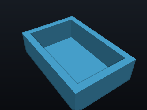
cad_move_face passesmin wall thickness 0.4 → 0.8 mm (limit 0.8 mm)
3D-print (Bambu X1 Carbon, 0.4 mm nozzle, PLA) an L bracket with a 0.6 mm rib and a 1.0 mm free-standing pin.
PASS · 3 iterationsThin wall and undersized pin — the rib is under the X1 Carbon pack's two-perimeter wall floor and the pin is under its printable-diameter floor.
Rule(s) under test: min_wall_thickness, x1c_min_pin_diameter
| iter | op applied | rule — measured vs limit | gate |
|---|---|---|---|
| 0 | (first build) | min wall thickness: 0.6 mm vs 0.84 mm FAIL min pin diameter (X1C): 1 mm vs 1.5 mm FAIL | 2 blocking |
| 1 | cad_move_face | min wall thickness: 0.84 mm vs 0.84 mm PASS min pin diameter (X1C): 1 mm vs 1.5 mm FAIL | 1 blocking |
| 2 | cad_move_face | min wall thickness: 0.84 mm vs 0.84 mm PASS min pin diameter (X1C): 1.5 mm vs 1.5 mm PASS | approved |
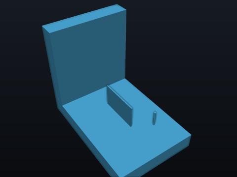
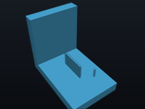
cad_move_facecad_move_face passesmin wall thickness 0.6 → 0.84 mm (limit 0.84 mm) · min pin diameter (X1C) 1 → 1.5 mm (limit 1.5 mm)
All 8, at a glance
More demos
All demos →
Pass PCB qualification before you build
One run over your board gives a UL and IPC readiness report, with the one change that fixes each finding.
5 checks pass · 1 fail PCB analysis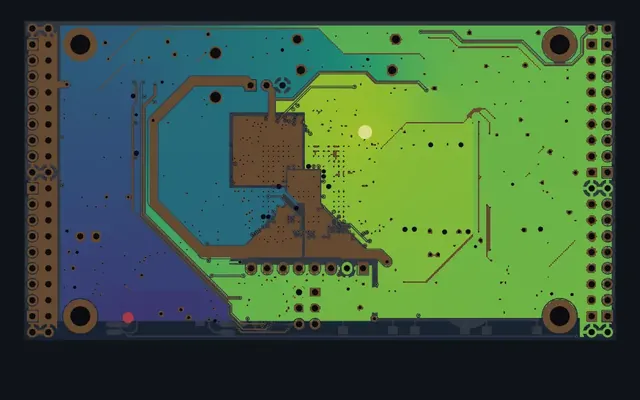
Your board, analysed before it is built
IR drop, impedance, weave skew, eye diagrams and via life, read straight from your board file.
Eyes open at 56 Gbps BOMblame pilot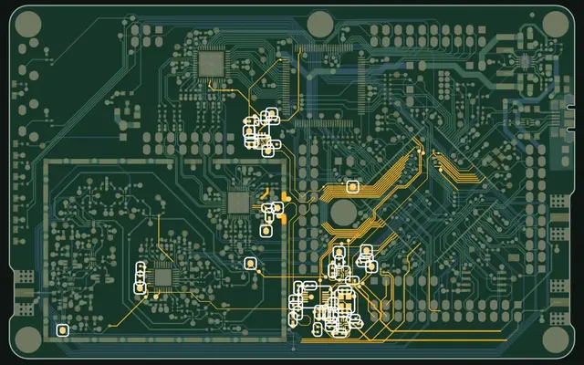
What each parts-list change did to the board
Every parts-list change in real open-hardware projects, traced to what it did to the circuit board.
162 commits read Drawings to STEP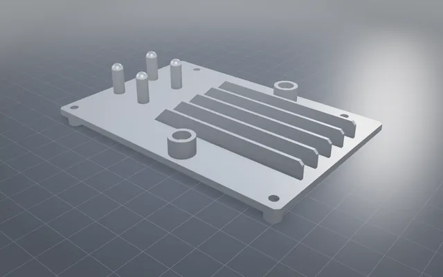
Manufacturing drawings in, STEP out, checked against the original
Real manufacturing drawings become exact 3D models, each matched against the official model.
6 of 6 NIST parts matchedBuild your own part with NativeCAD
Free for education and makers with a registered key · $200 per seat per year · Kernel SDK for products.