A drafting desk, twice: one sketch, two desks you could actually build
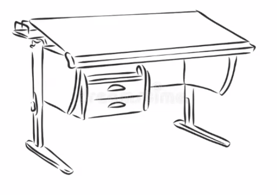
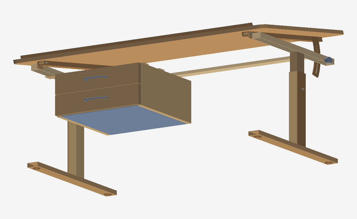
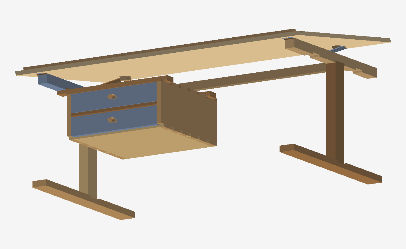
A line drawing of a tilting drafting desk with a hanging pedestal, turned into two complete, interference-checked assemblies: a powder-coated steel frame with an MDF top, and the same desk in solid oak where every structural joint is a dovetail that slides together by hand. Every part is a real B-rep solid with its own STEP file; every fastener has a hole to live in.
The whole brief, verbatim
Everything below was produced from these messages and a handful of screenshots. Each one is quoted as typed; open what it became for the trimmed account of the work it triggered.
- 1
(with a line sketch of a tilting drafting desk on cantilever legs with a two-drawer pedestal)make the most realistic desk you can using this as a referenceas realistic as possible for every sub assembly part so we could manufacture itwhat it became
v1 designed and built: 31 part numbers in steel RHS, MDF and melamine — pinned-height cantilever legs, tilting worktop on a hinge pin with a slotted quadrant lock, welded frame, hanging pedestal with two drawers. Every part its own STEP, an AP242 assembly with product structure, BOM, viewer and a first interference check that found five real clashes and fixed them. Along the way the MCP server kept resetting on cross-hole booleans, so the work moved to the kernel's headless batch API and an assembly merger script (logged as a kernel bug).
- 2let's do a separate version afterwards with real dovetail joins that would be assemblable
what it became
v2 generated as code (build_v2.py): the same desk in solid oak with sliding dovetails for leg↔foot, leg↔arm, rail↔arm, battens and pencil ledge, through dovetails on the pedestal carcass and drawer backs, half-blind dovetails on the drawer fronts — every male and female cut to the same 1:6 trapezoid. Notched-rack stay instead of the knob. 0.000 mm³ interference at 0/15/25°.
- 3
(with two viewer screenshots)log this tessellation as an issue (figure 1), hlr side on a few surfaces is not great (figure 2)what it became
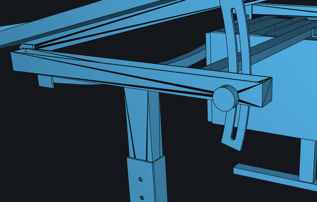
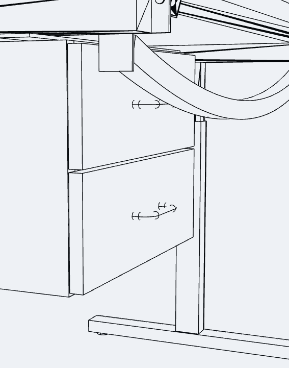
Two kernel bugs logged with the repro parts attached: the edge overlay drawing triangle diagonals across the planar faces of boolean output, and hidden-line mode drawing tessellation bands on cylindrical faces instead of one silhouette.
- 4did we get fasteners in it for everything to connect it all on both versions? can we show the explosion of assembly and some sweeps for the dovetails of how that will work to assemble?
what it became
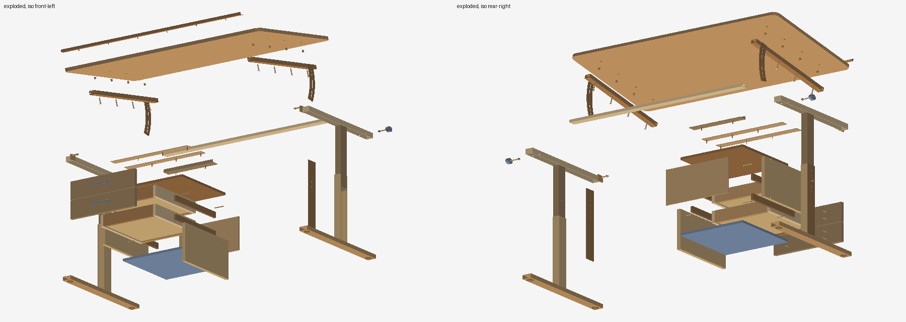
Honest answer was no. Every fastener was then modeled with its hole: v1 got M6 bolts and threaded inserts, confirmats, wood screws, countersunk ledge screws and hinge-pin circlips; v2 got brass butt hinges and sixteen screws. The faceted v1 tube parts were rebuilt exact with polygonal cross-holes. Exploded views for both, five animated slide-ins for the joinery, and a third kernel bug logged for polygon-prism booleans that fragment.
- 5let's also get the design and BOM made up for these desks*review and BOMafterwards turn this into a showcase for the site
what it became
DESK_DESIGN_REVIEW.md: comparison table, what changed under review, ergonomics, structure, mechanisms, joinery map, manufacturing routes, verification, open items, and enriched BOMs (material, stock, process, mass) for both desks. Then this page.
- 6
(with a screenshot circling the bowed front apron)get rid of the hanging support that bangs into the drawerswhat it became
Apron removed from both versions (and its housing from the oak arms); assemblies, viewers, exploded views, BOMs and the review regenerated. The rear rail carries the racking stiffness on its own.
- 7
(with a frame from the pedestal animation)does this slide through the dovetails on the one piece in this diagram?what it became
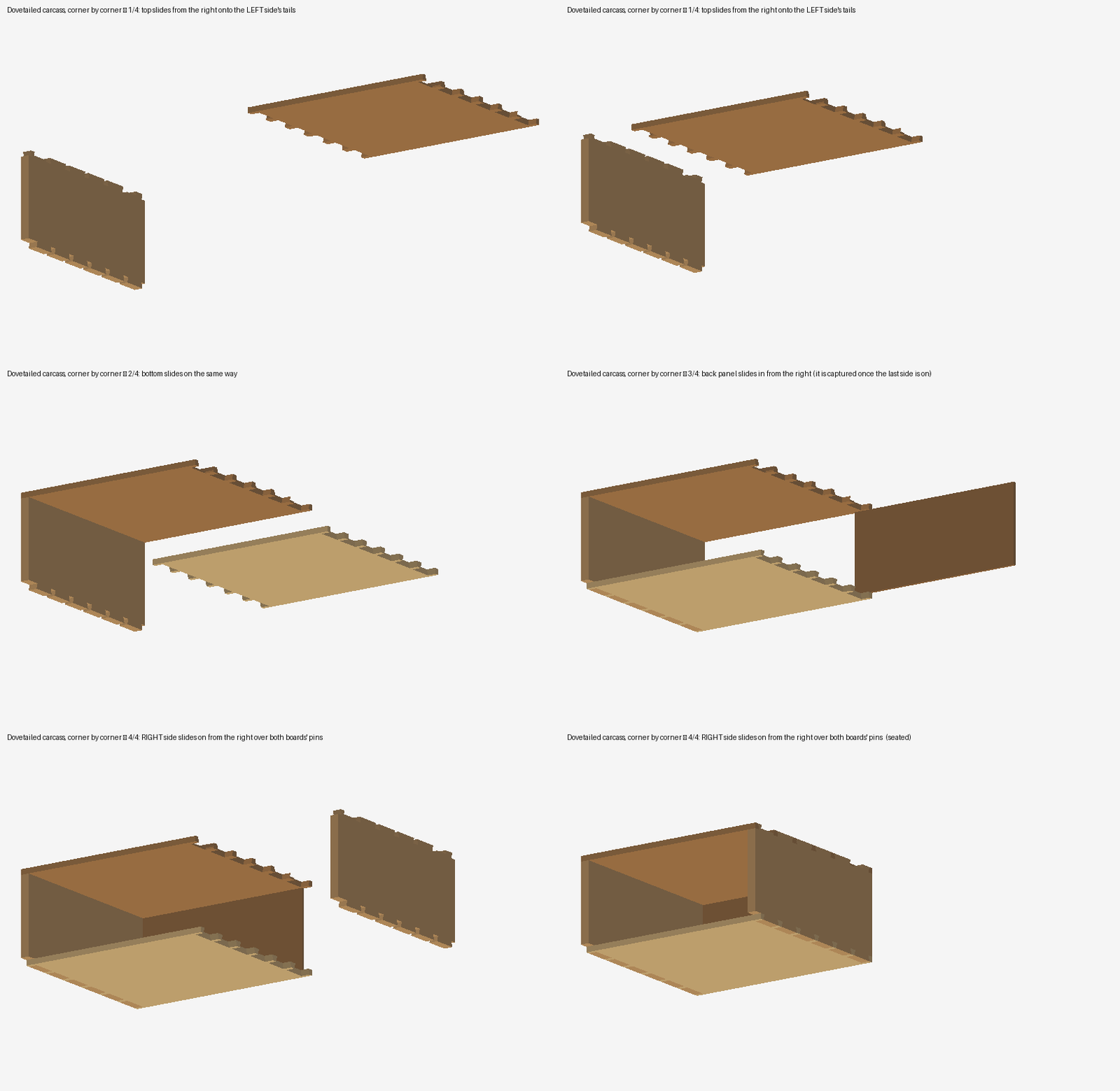
It didn't — the animation slid the top onto both sides' tails at once, which the sockets don't allow. Re-animated corner by corner: top and bottom onto the left side from the right, back panel in, right side last over both boards' pins. The drawer sequence was corrected the same way.
- 8got it on the site yet/
what it became
Page assembled in the site's shared skin (theme boot, tokens, nav strip, analytics), assets copied, hub card and nav link added across the showcase pages, pushed through deploy_site and checked live.
- 9
(with a screenshot of the viewer HUD listing every solid id)fix this text filling things upwhat it became
Viewer HUD now says “149 bodies” instead of printing every id (logged as a kernel viewer bug).
- 10put everything I prompted to get the table in the website example so they understand how much text became CAD and then this page, you can trim down your output into something that expands
what it became
This section.
How it was built
Each part was authored as a kernel recipe — an extrusion of a profile in a named plane, a box, a cylinder, a sweep — and cut with planar booleans: polygonal prisms for holes, tail-shaped prisms for dovetail sockets. One document per part, so every STEP holds exactly one watertight solid. The assembly is written with real product structure (one PRODUCT per part number, one NEXT_ASSEMBLY_USAGE_OCCURRENCE per instance with its placement), so a BOM reader sums quantities and a CAD system opens it as a tree rather than a soup of bodies.
The design changed under review. The first pass carried a bowed front apron under the worktop, straight from the sketch; it hung 32 mm in front of the drawer fronts and the drawers could not open, so it went. The first clash pass on v1 also found the tilt-lock stud inside the batten, the quadrant plate cutting the rear rail and the U-bolt hangers fouling the battens — each fixed and re-checked. In v2 the drawers were redesigned once it was clear that a half-blind dovetail socket must run out through the front's end grain or nothing can be slid together: an overlay front cannot be dovetailed, so v2 fronts are flush-fitted and the boxes ride on oak runners.
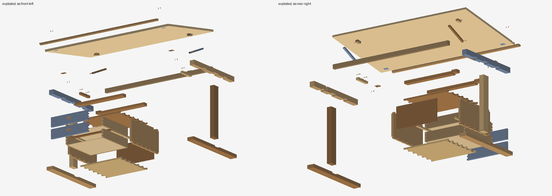
Exploded
How the dovetails go together
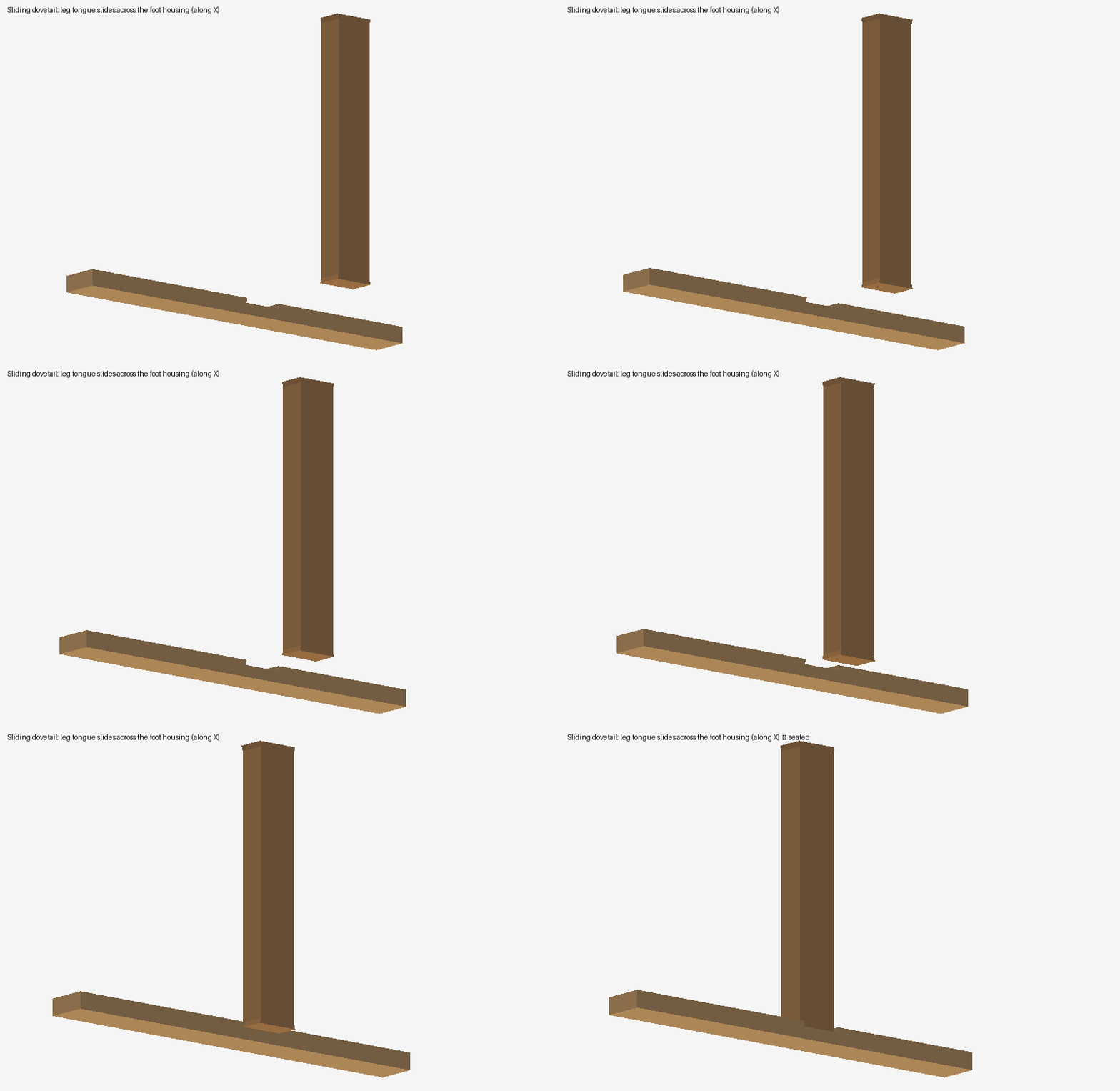
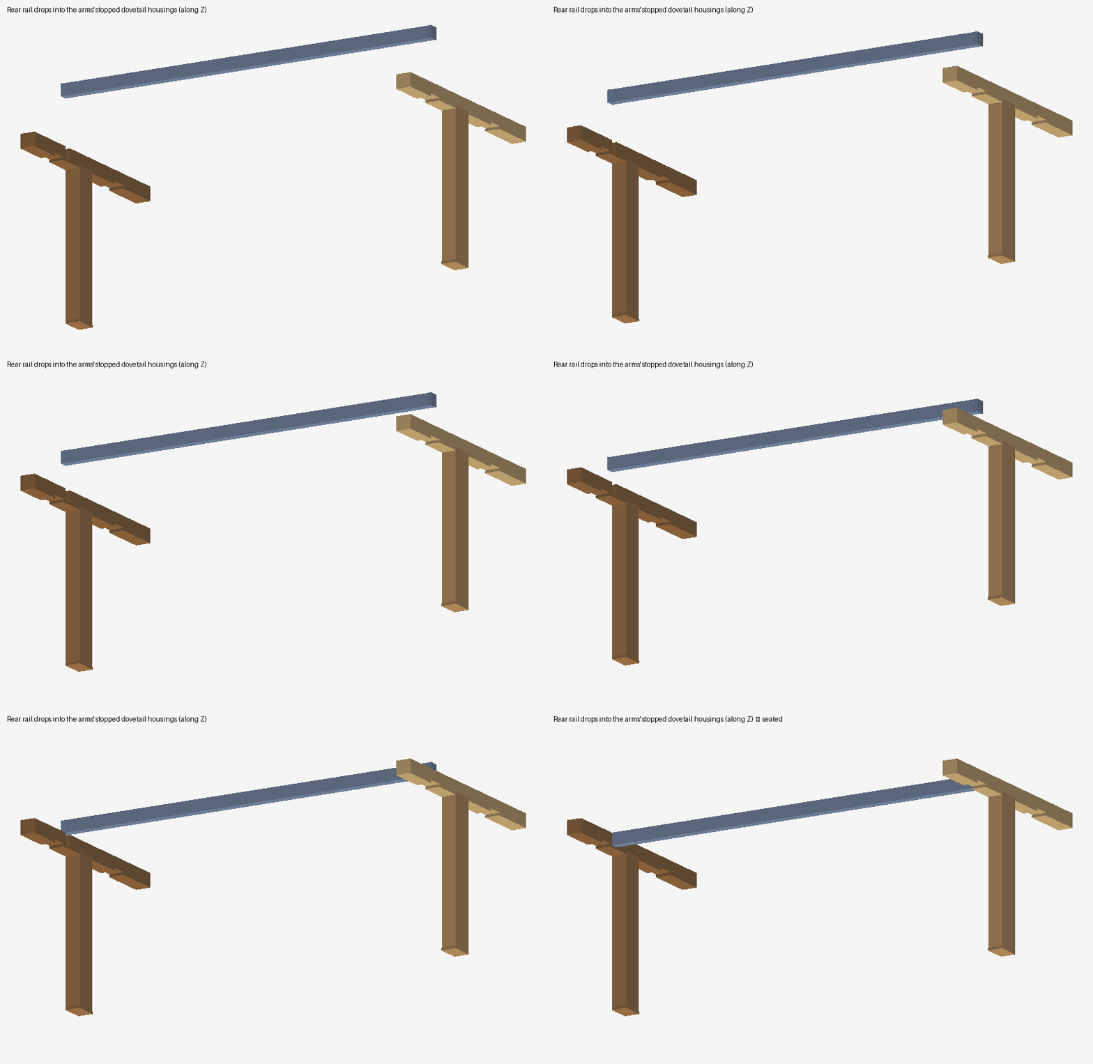
Every male tongue or tail and its female housing or socket are cut to the same 1:6 trapezoid, so the fit is line-to-line in the model (cut proud and fit by hand in the shop). The animations move the real part geometry from its approach to its seat, in the only order the joinery permits; the interference check reports each joint as face contact.
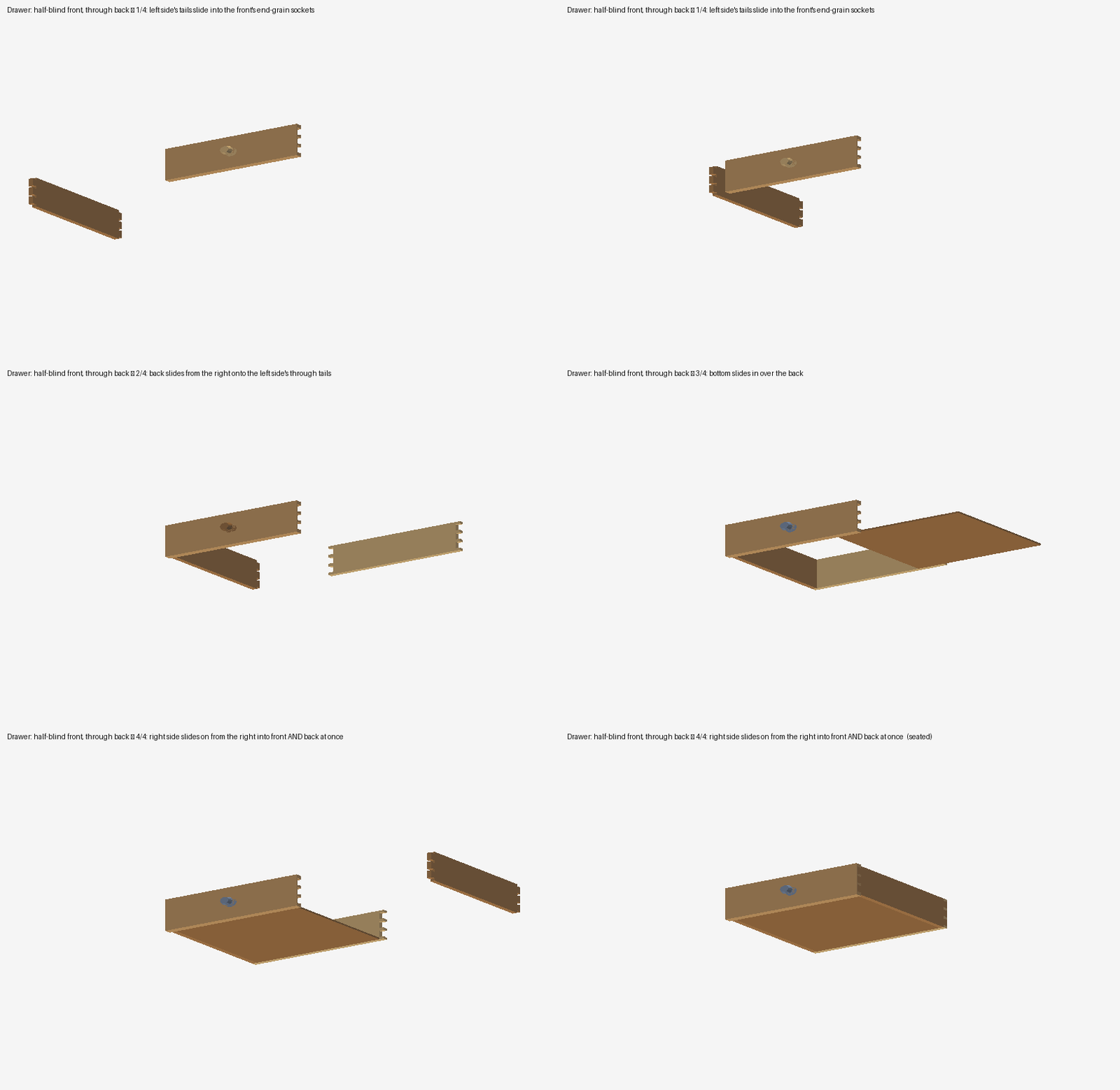
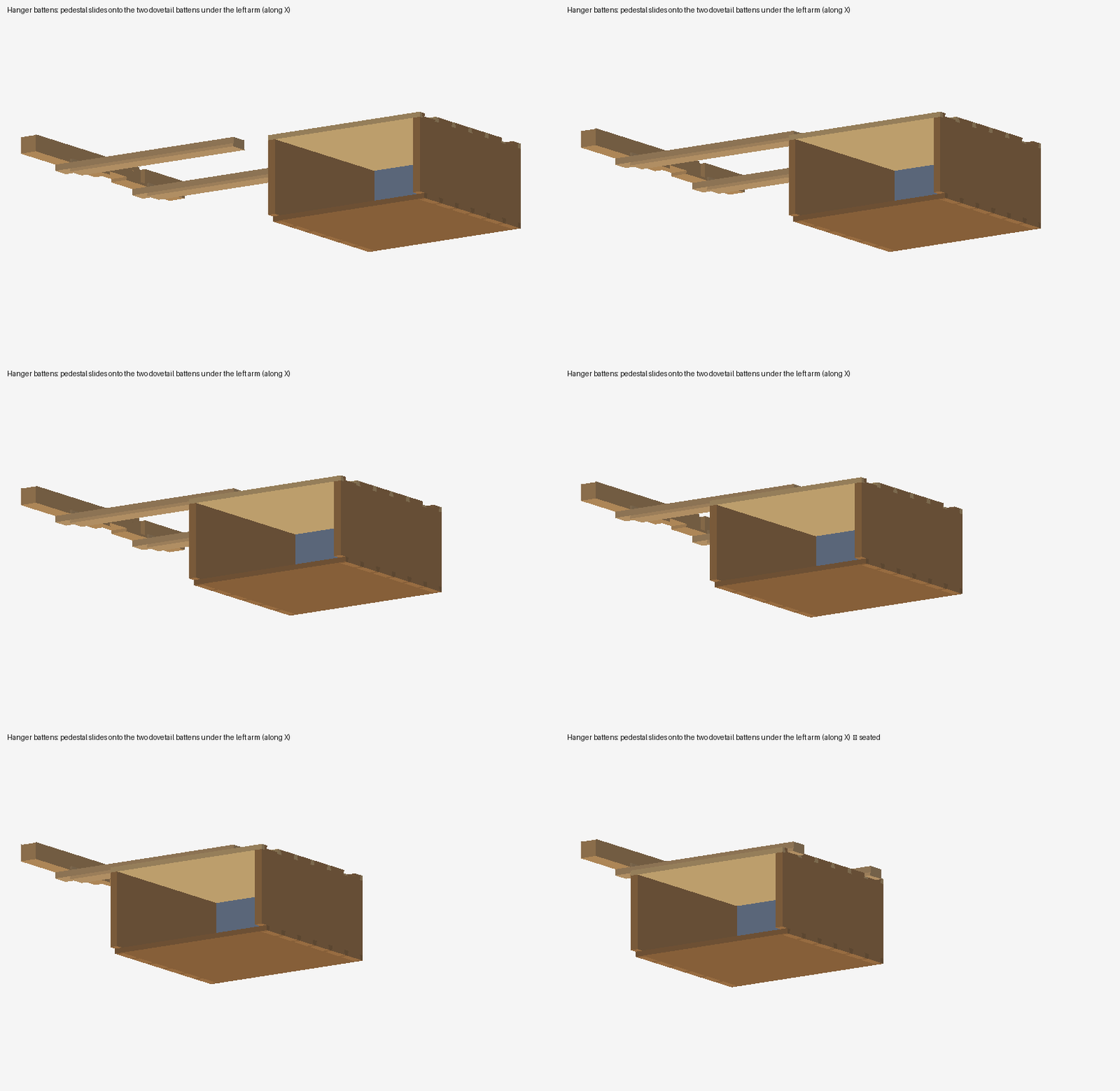
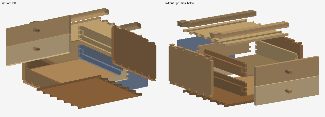
Turn it over yourself
Both assemblies in the kernel's own lightweight viewer: shaded, shaded with the real B-rep edges, hidden-line, or wireframe (keys 1–4). Left-drag orbits, wheel zooms.
v1 — steel frame
v2 — oak, dovetailed
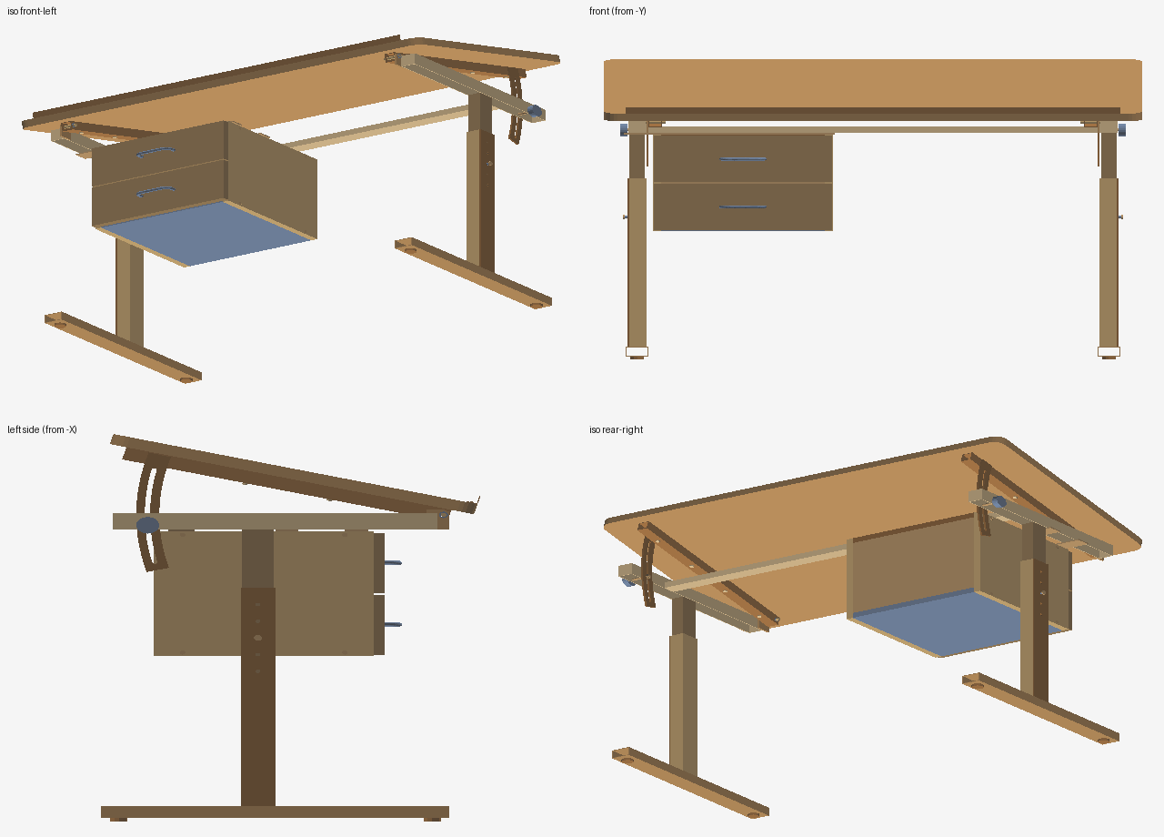
Four views
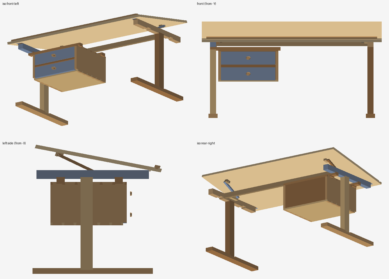
Bill of materials — v1 steel / MDF
Volumes come from the kernel's mass-properties pass over the STEP solids. Masses use 7.85 g/cm³ steel, 0.75 MDF, 0.68 melamine chipboard, 0.85 HDF; the slide envelopes are counted as solid steel (real slides ≈ 1 kg for four). Not modeled: slide screws, HDF brads, the height-pin R-clip.
| Part no. | Qty | Material | Stock / size | Process / notes | cm³ ea. | kg |
|---|---|---|---|---|---|---|
| P01_foot_RHS50x30x2 | 2 | steel | RHS 50×30×2, L600 | saw, deburr; welded to column channel | 182.4 | 2.86 |
| P02_glide_nylon_D30x8 | 4 | nylon | glide Ø30×8 | bought-in, press-fit | 5.6 | 0.03 |
| P03_column_channel_40x60x2 | 2 | steel | C-channel 40×60×2 (open outer face), L522 | laser + press-brake or cut RHS; welded to foot | 137.8 | 2.16 |
| P04_index_plate_4mm | 2 | steel | flat 4 mm, 60×522, 5× Ø8.5 @40 | laser-cut; welded closes the channel | 124.2 | 1.95 |
| P05_height_pin_D8x45 | 2 | steel | pin Ø8×45 | turned; height lock (R-clip, not modeled) | 2.3 | 0.04 |
| P05b_pin_head_D14x4 | 2 | steel | head Ø14×4 | welded to P05 | 0.6 | 0.01 |
| P06_inner_column_RHS34x54x2 | 2 | steel | RHS 34×54×2, L480, Ø8.5 cross hole | saw, drill; welded to P07 | 161.1 | 2.53 |
| P07_top_arm_RHS40x40x2 | 2 | steel | RHS 40×40×2, L560, Ø8.5 cross hole | saw, drill; welded to P06 | 95.1 | 1.49 |
| P08_hinge_bracket_5mm | 2 | steel | plate 5 mm 60×48 (stepped), Ø10.2 | laser-cut; welded to arm inner face | 9.1 | 0.14 |
| P09_top_batten_RHS30x30x2 | 2 | steel | RHS 30×30×2, L580, Ø10.2 + 4× Ø7.2 | saw, drill; M6 bolted to worktop inserts | 129.0 | 2.02 |
| P10_hinge_pin_D10x45 | 2 | steel | pin Ø10×45 | turned; hinge axis, 2× circlips | 3.5 | 0.06 |
| P11_tilt_quadrant_5mm | 2 | steel | plate 5 mm, R490–530 sector, 9 mm arc slot | laser-cut; welded to batten | 45.6 | 0.71 |
| P12_lock_knob_D40 | 2 | pa | star knob Ø40, M8 insert | bought-in | 18.8 | 0.05 |
| P13_knob_stud_M8x54 | 2 | steel | M8 stud ×54 | bought-in | 2.7 | 0.04 |
| P14_hex_nut_M8 | 2 | steel | M8 hex nut | bought-in | 0.6 | 0.01 |
| P16_cross_rail_RHS40x20x2 | 1 | steel | RHS 40×20×2, L1010 | saw; welded between arms | 226.2 | 1.78 |
| P18_worktop_MDF25_1200x650 | 1 | mdf | MDF 25 mm 1200×650 R30, laminated; 8× Ø10.6 insert holes, 6× Ø4 pilots | CNC route, edge-band | 19468.1 | 14.60 |
| P19_pencil_ledge_alu_20x20x2 | 1 | alu | angle 20×20×2, L1100, 6× Ø3.8 | saw, drill; 6× 3.5×16 csk screws | 83.5 | 0.23 |
| P20_pedestal_side_MFC18 | 2 | mfc | MFC 18 mm 380×300, 4× Ø7.2 + csk | panel saw, edge-band, drill | 2048.5 | 2.79 |
| P21_pedestal_top_MFC18 | 1 | mfc | MFC 18 mm 364×380 (top), pilots | panel saw, edge-band | 2482.5 | 1.69 |
| P21b_pedestal_bottom_MFC18 | 1 | mfc | MFC 18 mm 364×380 (bottom), pilots | panel saw, edge-band | 2484.2 | 1.69 |
| P22_pedestal_back_HDF6 | 1 | hdf | HDF 6 mm 364×264 | panel saw; brads (not modeled) | 576.6 | 0.49 |
| P23_drawer_front_MFC18 | 2 | mfc | MFC 18 mm 396×144, 4× Ø4 pilots, 2× Ø10.2 handle holes | panel saw, edge-band, drill | 1023.8 | 1.39 |
| P24_drawer_side_16x90x350 | 4 | mfc | drawer side 16 mm 350×90 | panel saw | 504.0 | 1.37 |
| P25_drawer_back_16x90x306 | 2 | mfc | drawer back 16 mm 306×90 | panel saw | 440.6 | 0.60 |
| P25b_drawer_subfront_16x90x306 | 2 | mfc | drawer sub-front 16 mm 306×90, 4× Ø4.5 | panel saw, drill; 4× 4×35 screws into the front | 439.6 | 0.60 |
| P26_drawer_bottom_HDF6 | 2 | hdf | HDF 6 mm 306×318 drawer bottom | panel saw; glue + brads | 583.8 | 0.99 |
| P27_drawer_slide_350_ballbearing | 4 | steel | ball-bearing slide 350 mm (envelope 12.7×45) | bought-in with its own 8 screws (not modeled) | 200.0 | 6.28 |
| P28_bow_handle_D10_96cc | 2 | steel | bow handle Ø10 wire, 96 cc, legs 37 long | bought-in; legs epoxied into Ø10.2 blind holes | 12.2 | 0.19 |
| P30_hanger_bar_40x4_flat | 2 | steel | flat 40×4, L470, 3× Ø5 | laser-cut; welded under left arm | 75.0 | 1.18 |
| P31_rear_support_angle_40x40x4 | 1 | steel | angle 40×40×4, L300, 2× Ø5 | saw, drill; welded to rear rail | 76.6 | 0.60 |
| P32_hex_bolt_M6x45 | 8 | steel | hex bolt M6×45 | bought-in (worktop ↔ batten) | 1.6 | 0.10 |
| P33_threaded_insert_M6x15 | 8 | steel | threaded insert M6×15 | bought-in, screwed into MDF | 0.7 | 0.04 |
| P34_wood_screw_4.5x30 | 8 | steel | wood screw 4.5×30 | bought-in (hanger bars, rear angle → carcass) | 0.6 | 0.04 |
| P35_wood_screw_4x35 | 8 | steel | wood screw 4×35 | bought-in (drawer sub-front → front) | 0.5 | 0.03 |
| P36_wood_screw_3.5x16_csk | 6 | steel | wood screw 3.5×16 csk | bought-in (pencil ledge) | 0.2 | 0.01 |
| P37_circlip_DIN471_10 | 4 | steel | circlip DIN 471 – 10 | bought-in (hinge pins) | 0.1 | 0.00 |
| P38_confirmat_7x50 | 8 | steel | confirmat 7×50 | bought-in (carcass) | 2.1 | 0.13 |
| 38 part numbers · 111 pieces | 50.9 | |||||
Bill of materials — v2 solid oak
Oak at 0.72 g/cm³, brass 8.5. Sixteen screws, two hinges, two dowels and two pins are the only hardware; everything else is joinery. Glue, drawer-bottom grooves and back-panel brads are shop details not modeled.
| Part no. | Qty | Material | Stock / size | Process / notes | cm³ ea. | kg |
|---|---|---|---|---|---|---|
| V01_foot_oak_60x40x600_L | 1 | oak | 60×40×600, dovetail housing across the top | plane, router housing | 1395.4 | 1.00 |
| V01_foot_oak_60x40x600_R | 1 | oak | 60×40×600, dovetail housing across the top | plane, router housing | 1395.4 | 1.00 |
| V02_leg_oak_40x60x644_L | 1 | oak | 40×60×644 incl. 12 mm tongues top & bottom | plane, router tongues | 1547.5 | 1.11 |
| V02_leg_oak_40x60x644_R | 1 | oak | 40×60×644 incl. 12 mm tongues top & bottom | plane, router tongues | 1547.5 | 1.11 |
| V03_arm_oak_40x60x560_L | 1 | oak | 40×60×560; 3 underside housings, rail housing, hinge mortise, pilots | plane, router, chisel | 1256.9 | 0.91 |
| V03_arm_oak_40x60x560_R | 1 | oak | 40×60×560; 3 underside housings, rail housing, hinge mortise, pilots | plane, router, chisel | 1256.9 | 0.91 |
| V04_rear_rail_oak_22x52x1034 | 1 | oak | 22×52×1034, dovetail tongues both ends | plane, router | 1185.4 | 0.85 |
| V06_worktop_oak_1200x650x25 | 1 | oak | 1200×650×25 glued-up panel; ledge groove, hinge mortises, pilots | glue-up, plane, router groove | 19360.3 | 13.94 |
| V07_pencil_ledge_oak_28x18x1140 | 1 | oak | 28×18×1140, sliding-dovetail tongue | plane, router | 702.2 | 0.51 |
| V08_stay_rack_oak_22x30x120_L | 1 | oak | 22×30×120 stay rack, 4 notches, 2× Ø4.2 | bandsaw, drill | 69.0 | 0.05 |
| V08_stay_rack_oak_22x30x120_R | 1 | oak | 22×30×120 stay rack, 4 notches, 2× Ø4.2 | bandsaw, drill | 69.0 | 0.05 |
| V09_stay_strut_oak_16x20x224_L | 1 | oak | 16×18×216 stay strut, 2× Ø10.6 | plane, drill | 59.5 | 0.04 |
| V09_stay_strut_oak_16x20x224_R | 1 | oak | 16×18×216 stay strut, 2× Ø10.6 | plane, drill | 59.5 | 0.04 |
| V10_pivot_block_oak_22x40x25_L | 1 | oak | 22×40×25 pivot block, Ø10.6 + 2× Ø4.4 | saw, drill | 19.4 | 0.01 |
| V10_pivot_block_oak_22x40x25_R | 1 | oak | 22×40×25 pivot block, Ø10.6 + 2× Ø4.4 | saw, drill | 19.4 | 0.01 |
| V11_stay_dowel_beech_D10x41_L | 1 | beech | dowel Ø10×41 | bought-in dowel | 3.2 | 0.00 |
| V11_stay_dowel_beech_D10x41_R | 1 | beech | dowel Ø10×41 | bought-in dowel | 3.2 | 0.00 |
| V12_pivot_pin_beech_D10x44_L | 1 | beech | pin Ø10×44 | bought-in dowel | 3.4 | 0.00 |
| V12_pivot_pin_beech_D10x44_R | 1 | beech | pin Ø10×44 | bought-in dowel | 3.4 | 0.00 |
| V13a_brass_butt_hinge_38x40_fixed_half | 2 | brass | butt hinge 38×40×2 fixed half + knuckle Ø8 | bought-in | 3.3 | 0.06 |
| V13b_brass_butt_hinge_38x40_top_leaf | 2 | brass | butt hinge top leaf 38×25×2 | bought-in (same hinge) | 1.8 | 0.03 |
| V14_brass_screw_3.5x16_csk | 8 | brass | screw 3.5×16 csk | bought-in (hinges) | 0.2 | 0.01 |
| V15_wood_screw_4x30 | 4 | steel | wood screw 4×30 | bought-in (racks) | 0.5 | 0.01 |
| V16_wood_screw_4x40 | 4 | steel | wood screw 4×40 | bought-in (pivot blocks) | 0.6 | 0.02 |
| V20_pedestal_side_oak_18x380x300 | 2 | oak | 18×380×300, 6 tails each end, 2 batten notches | plane, saw + chisel tails | 1976.5 | 2.85 |
| V21_pedestal_top_oak_18x400x380 | 1 | oak | 18×400×380 top, 12 sockets, 2 dovetail housings | plane, router, chisel | 2171.5 | 1.56 |
| V22_pedestal_bottom_oak_18x400x362 | 1 | oak | 18×400×362 bottom (set back 18), 12 sockets | plane, chisel | 2426.3 | 1.75 |
| V23_pedestal_back_oak_6x364x264 | 1 | oak | 6×364×264 back panel | resaw/plane; brads | 576.6 | 0.41 |
| V24_drawer_front_oak_18x120x362 | 2 | oak | 18×120×362 flush front, 6 half-blind sockets, Ø10.6 knob hole | plane, router, chisel | 754.5 | 1.09 |
| V25_drawer_side_oak_12x110x351 | 4 | oak | 12×110×351 side, half-blind tails front, through tails back | plane, saw + chisel | 452.9 | 1.30 |
| V26_drawer_back_oak_12x110x362 | 2 | oak | 12×110×362 back, 6 sockets | plane, chisel | 456.0 | 0.66 |
| V27_drawer_bottom_oak_6x338x325 | 2 | oak | 6×338×325 bottom | resaw/plane; glue | 659.1 | 0.95 |
| V29_knob_oak_D32 | 2 | oak | turned knob Ø32, Ø10 tenon | lathe; glue | 20.1 | 0.03 |
| V30_hanger_batten_oak_40x22x470 | 2 | oak | 40×22×470 hanger batten, tongues top (arm end) & bottom (full) | plane, router | 653.0 | 0.94 |
| V31_drawer_runner_oak_20x18x345 | 2 | oak | 20×18×345 drawer runner | plane; glue | 124.2 | 0.18 |
| V32_drawer_rail_oak_18x22x364 | 1 | oak | 18×22×364 drawer rail | plane; glue | 144.1 | 0.10 |
| 36 part numbers · 61 pieces | 33.5 | |||||
What the review settled
- Ergonomics. v1 spans 695–855 mm at the front edge (seated to standing-lean); v2 is a fixed 745 mm drafting height. Tilting about the front edge keeps the pencil ledge where the hand expects it and lifts the rear by up to 275 mm.
- Structure. Columns sit 55–60 % back on 600 mm feet, so a lean on the front edge stays inside the footprint. The v1 index plate carries the pin in double shear; v2's 1:6 sliding dovetails resist the leg being levered off the foot.
- Pedestal. Hangs 400 mm outboard on two bars — welded steel flats in v1, dovetailed oak battens in v2 — with a rear tie to the cross rail in v1. Around 100 N·m on the bars at a loaded 25 kg pedestal.
- Mechanisms. v1: slotted quadrant on R510.6 clamped by an M8 star knob; add a nylon washer and a serrated washer. v2: notch positions on the rack solved for 10/15/20/25° with a 200 mm strut so the dowel seats with 12 mm to spare under the top.
- Assembly order (v2). Feet → legs → battens started in the left arm → arms → rear rail dropped in → hinges and worktop → pedestal slid onto the battens → pencil ledge slid in → racks, blocks and struts screwed. Carcass and drawers corner by corner, as animated above.
What the kernel learned
Build your own — install NativeCAD for Claude today
Both desks came out of a conversation with Claude with the NativeCAD MCP installed: 188 words of prompts, two manufacturable assemblies. The same kernel installs in about a minute and is free for personal, academic and research work with a free registered key (email confirmation, one form at featureboard.ai/register); the evaluation loop needs no key at all.
Claude Desktop: open the downloaded .mcpb and it installs as an extension.
Claude chat: open the .plugin, or attach it in a chat and press Save.
Claude Code and other MCP clients: one npx line (the tarball today, the registry name once published). Have a product you want modeled to
manufacturing detail like this? Book a call and bring the sketch.
Files
More demos
All demos →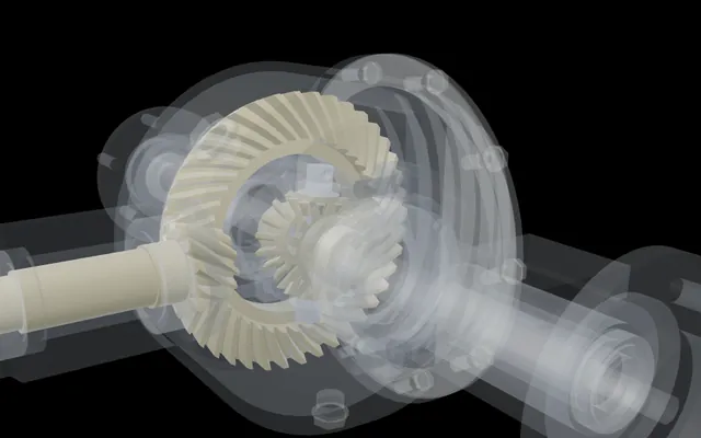
One wheel held, the other turns twice as fast
A complete rear differential with every bolt modelled, driven only by its mates, its feature tree open.
59 parts · 123 mates Space Program
Fly what NativeCAD builds, from an A-10 to a Saturn V
NativeCAD-built aircraft and spacecraft on a real-scale world, from a gun run to a Moon landing.
18 vehicles you can fly FoDES desk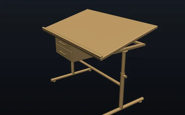
A drafting desk built by conversation, from one line sketch
Hinge, gas struts, telescoping legs and every fastener, built by talking to an AI agent.
202 bodies, by conversation GE bracket
The GE jet engine bracket, lighter and carrying every load
The classic titanium bracket optimised and offered to print, cast, machine or weld, with STEP to download.
84.3% lighterBuild your own part with NativeCAD
Free for education and makers with a registered key · $200 per seat per year · Kernel SDK for products.