The checks your checker forgets.
An interference check says this car transaxle goes together: 0 clashes across 620 touching part pairs. It does not say that, as drawn, the output shaft's taper bearings can be squeezed anywhere from 0.000 to 0.710 mm when the window is 0.130 to 0.180 mm. It does not notice a flange bolt one length short, holding the case on by too little aluminium thread. NativeCAD runs those checks on the 175-part 3-D assembly itself: tolerance stacks by worst case, RSS and 20,000 simulated builds, and a full audit of all 30 bolts, screws and dowels that hold it together.
Pick a check. See what drives it.
Each stack chains the dimensions that decide one fit. The parts that carry them glow; tap a dimension to light just that one. Tap any part in the view to read it, and light up the hardware with the fastener buttons.
The problem it found
The output shaft runs in two taper roller bearings that must be squeezed together by 0.130 to 0.180 mm. The chain that sets it crosses the case flange: a bearing seat in the clutch housing, the flange, a bearing seat in the transaxle case, against two bought-in bearings and the shaft between them. Too little squeeze and the shaft walks under the helical thrust; too much and the bearings run hot.
The stack fails
Still fails
Hold every machined span to ±0.01 mm and the two bearing widths alone still spread 0.400 mm across a 0.050 mm window.
A spacer, picked at assembly
Measure the gap under the rear bearing cup, pick the spacer from a range in 0.03 mm steps. The castings, the bearings and the shaft drop out of the stack.
| Bearing preload, mm | As drawn | Spacer picked | Requirement |
|---|
The other two stacks pass — and now you know by how much
First-gear backlash Pass
Bore centres in both castings, the input bearings' play and runout, the output bearings' runout, all through the mesh geometry: worst case 0.086 to 0.160 mm against at least 0.075 mm. 0% of simulated builds fall below it.
Flange bolt clearance Pass
Hole positions on both castings, dowel float and the bolt's own thread tolerance: at the worst corner of the tolerance box a flange bolt still clears its hole by 105 µm.
Every fastener that holds it together
The case is two aluminium castings on one flange, closed by an end cover, with a retainer plate on the input bearing. Each joint's bolts are checked where they sit in the model: thread engaged against what cast aluminium needs (2 × d), thread strip from the casting's own strength, whether a bolt bottoms, the hole series, edge distance and wall, head pressure on the aluminium, preload and tightening torque, the clamp left against the gear loads trying to open the joint, and room for the socket.
We planted 4 mistakes. It caught every one.
A copy of the assembly with mistakes of the kind a reviewer sees on real jobs: the wrong bolt out of the bin, a bracket added after the bolt pattern was fixed, a drilling put in too close. The audit reported exactly these, and nothing else. Each one opens on the bolt in question.
And on the design itself
All 30 fasteners
| Fastener | Thread engaged | Hole left under the tip | Torque and preload | Edge / wall | Socket room | Result |
|---|
Take the report
Every stack with its contributors, tolerances and where each tolerance came from; every joint and every fastener with its numbers; the finding and the fix.
Send us one of your assemblies
Send a STEP file and name the fits you care about. We run the stacks and the fastener audit on it and send back this report for your parts — the problem, the contributor that causes it, and the fix.
Send us an assemblyOr open NativeCAD in your browser.
More demos
All demos →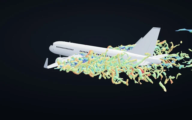
A320neo airflow, simulated on one gaming GPU
A large-eddy simulation of the vortices around our airliner on approach, solved on one gaming graphics card.
6.6 min per case on one GPU FEA loop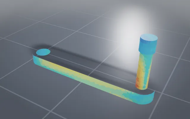
Finite-element analysis your agent can run
Stress and vibration results from the same AI session that built the part, with the peak and its margin.
6 designs solved in FEA DFM design loop
The DFM design loop closes its own findings
Parts that break a machining, moulding, sheet or print rule come back fixed from the checker's own advice.
8 of 8 parts fixed Drawings to STEP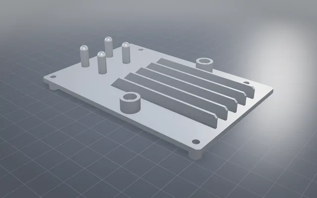
Manufacturing drawings in, STEP out, checked against the original
Real manufacturing drawings become exact 3D models, each matched against the official model.
6 of 6 NIST parts matchedBuild your own part with NativeCAD
Free for education and makers with a registered key · $200 per seat per year · Kernel SDK for products.