NativeCAD MCP server · public since 0.13.0
Finite-element analysis your agent can run
The same session that builds the part can load it, restrain it and ask what happens — and get an answer it can act on. Three tools, cad_fea_case, cad_fea_run and cad_modal, write a real solver deck straight from the B-rep, run CalculiX, and hand back JSON: the peak stress, where it sits and on which face, the safety factor, the natural frequencies, the mode shapes. Boundary conditions are face ids the model already knows, so a restraint is one line, not a click. No solver licence, no meshing session, no card deck to learn. Below: a bicycle crank arm pocketed against the ISO 4210-8 pedal load until the loop finds the wall, a steel bar checked against the textbook, and an L-bracket fillet ladder read the way the driver reads it.
Install: npx -y https://featureboard.ai/nativecad/releases/nativecad-mcp-0.27.0.tgz, then put ccx on PATH (apt install calculix-ccx, brew install calculix-ccx, or conda-forge calculix) or point CADSOLVER_CCX at it. No solver installed ⇒ cad_fea_run answers solver_missing with those routes; it never fabricates a stress. Modal cases can also go to MYSTRAN through the same case directory.
A crank arm, pocketed until it is just strong enough
The part everyone lightens: a 172.5 mm bicycle crank arm in Aluminium 6061-T6 — a 36×16 mm obround (so the spindle end is the boss and there is no re-entrant notch to blend), Ø24 spindle bore, one obround pocket on the inboard face with r1.5 floor fillets. The load is the one ISO 4210-8 actually applies: 1800 N vertical with the crank at 45°, through the pedal, 65 mm outboard of the crank face — so the loop models the pedal spindle and puts the load on the pedal body as a bearing load, and that 65 mm lever turns it into bending plus torsion. An open pocket is a thin-walled open section, which is exactly where torsion bites, and that is why the web under the pocket is the design variable: depth 0/2/3/4/6/8 mm, web 16/14/13/12/10/8 mm. The wall is SF ≥ 1.5 on yield — a static screen, not the standard's 100,000-cycle fatigue test; the objective is the arm's mass (weighed without the pedal). Kernel f12a690f.
all 6 solved designs load side by side when this reaches the screen
| web | arm mass | arm peak σvM | where (x, y, z) | body peak, pedal in | SF | ≥ 1.5 | tets | solve | |
|---|---|---|---|---|---|---|---|---|---|
| 0 | 16 | 292.7 | 140.5 | spindle end (11, 8, 1) | 328.1 pedal stub | 1.97 | pass | 18,657 | 21.7 s |
| 2 | 14 | 275.7 | 160.1 | pocket end (31, 12, 0) | 316.9 pedal stub | 1.72 | pass | 19,732 | 24.3 s |
| 3 | 13 | 267.1 | 173.5 | pocket end (30, 12, 0) | 357.6 pedal stub | 1.59 | pass | 19,434 | 20.3 s |
| 4 | 12 | 258.4 | 217.9 | pocket end wall (31, 11, 1) | 334.4 pedal eye | 1.27 | fail | 19,628 | 19.5 s |
| 6 | 10 | 241.1 | 238.1 | pocket end (34, 12, 1) | 405.2 pedal stub | 1.16 | fail | 20,169 | 18.3 s |
| 8 | 8 | 223.7 | 330.7 | pocket end wall (33, 12, 1) | 458.5 pedal eye | 0.83 | fail | 21,231 | 19.9 s |
mm, g, MPa; Sy 276 MPa; the highlighted row is the design the viewer shows.
The loop's answer is the 3 mm pocket: 267.1 g against 292.7 g for the solid arm, 25.6 g (9 %) off with the peak at 173.5 MPa on the pocket end and SF 1.59 against Sy 276 MPa. At 4 mm (a 12 mm web) the SF drops to 1.27 and the loop stops banking mass. Every row is a solved case with its case directory beside it; the “where” column is the solver's peak coordinate placed on the geometry the loop itself built, so “pocket end” is the inboard face at the pocket's end arc, “pocket end wall” is that wall itself and “pocket floor” the floor or its fillet — not a guess from a picture.
Two peaks are reported on purpose. The arm peak is the judged one: the element-averaged integration-point von Mises over every element of the arm, read from the solver's own .dat with the modelled pedal left out — the spindle is a steel part in reality and is drawn here in the arm's aluminium, monolithic with it, only to carry the load 65 mm out, so its own bending stress and the sharp corner where it meets the crank face are artefacts of the stand-in. The body peak beside it is what cad_fea_run reported for the whole body, pedal included, so nothing is hidden: it is always on the pedal stub, and it is why the loop judges by zone rather than by the global maximum. Every solve here was cut with meshQuality: true (the boundary re-cut and the tet-quality pass, public on cad_fea_run since this page): the first two runs of this loop, on the plain mesher's 50–60 % slivers, put the arm's peak in a tet of shape quality 4×10⁻⁵ — a number that belonged to the mesh, not the part.
The first cut of this loop — a 26 mm arm on a Ø36 boss, the load applied in the crank plane at the pedal eye — failed at SF 1.19 before any pocket was cut, with the peak in the 34° arm/boss notch. The readout said where; the geometry was redrawn without the notch and the load was moved to where the standard puts it. That is the loop doing its job.
Built in 10 calls, screened in two
cad_extrude_profilearm: 172.5 mm obround, 36 wide, 16 thick · 12 ms · 6 facescad_drill_holespindle bore Ø24 · 3285 ms · 8 facescad_extrude_profileinboard pocket, depth 3 · 61 ms · 6 facescad_boolean_subtractpocket the inboard face — web 13 mm · 217 ms · 13 facescad_fillet_edgespocket-floor fillets r1.5 · 275 ms · 17 facescad_copythe arm alone, for cad_mass_properties · 225 mscad_extrude_profilepedal spindle stub Ø16, 0..70 mm · 41 ms · 4 facescad_boolean_unionarm ∪ pedal stub · 303 ms · 20 facescad_extrude_profilepedal body Ø20, 70..88 mm (centre 79 = 16 + 65) · 35 ms · 4 facescad_boolean_unionarm ∪ stub ∪ pedal body · 451 ms · 23 faces
then cad_measure ray-fires from the spindle axis and the pedal axis to collect the clamped bore and the loaded pedal body (no ids typed in), cad_fea_case with spindle bore clamped and ISO 4210-8 pedal load, 1800 N on the pedal body 65 mm out, crank at 45° along [-0.707,-0.707,0], cad_fea_run, cad_mass_properties on the arm alone. 6 solves, 124.0 s of solver time for the ladder.
Five calls, one design loop
Build, restrain, solve, read the verdict, move the design variable, repeat — with provenance for every iteration. This is the loop an agent runs through the MCP surface. The arguments below are the ones the driver actually sent for the r = 2 mm iteration, read from loop.json.
cad_extrude_profilethe L-bracket — a 60×40×8 base with an 8×50 leg, one profile, one depth. 7 ms, 32,640 mm³, 8 faces, watertight.
{"profile":{"outer":[[0,0],[60,0],[60,8],[8,8],[8,50],[0,50]]},"depth":40,"plane":{"origin":[0,0,0],"xAxis":[1,0,0],"yAxis":[0,0,1]}}cad_fillet_edgesthe inside-corner fillet, selected by what it is (
concave, along[0,1,0]) rather than by id — the one design variable the loop sweeps. 32,674 mm³, 9 faces.{"of":"$0","radius":2,"edges":[{"direction":[0,1,0],"convexity":"concave"}]}cad_fea_caserestraints and loads on face ids: the base base bolted down (
#282), 400 N pull on the leg along[1,0,0](#310), materialAISI 1018 steelfrom the preset table (E 205 GPa, ν 0.29, Sy 370 MPa), target 8,000 cells. The case directory it writes —body.stl, onepatch_<n>.stlper boundary condition sliced from the same tessellation,case.json— is the contract every solver adapter reads.cad_fea_runsolver: "auto"— the C3D10 deck is written,ccxruns, the.frdis read back. 14,104 tets, 24.8 s on the solve.- read the verdict
not a number, a sentence with its evidence:
calculix: max von Mises 57.5 MPa at (5.9, -12.6, 7.1) mm vs yield 370.0 MPa → SF 6.43 max displacement 0.0343 mm (face #258)— plusonFillet: true, the nodal peak beside the integration-point peak, the cell count and the wall time. The driver compares it with the wall (SF ≥ 5) and moves the radius.
Checked against the textbook
A 120×20×4 mm AISI 1018 steel bar, one end face fixed (#127 from cad_body_topology), cad_modal for six modes. Three calls; the deck was written in a sandbox with no solver (deckOnly: true) and solved on a workstation with CalculiX 2.21 — 29,022 nodes, 17,697 C3D10 tets on the quality mesh (< 0.01 % slivers, min dihedral 9.6°), 33.5 s for mesh and solve together.
Three references, each computed by the page generator from the case's own E = 205 GPa, ν = 0.29, ρ = 7870 kg/m³ and the deck's own bounding box: Euler–Bernoulli (the slender beam), Timoshenko (adds shear deformation and rotary inertia, κ = 10(1+ν)/(12+11ν) = 0.849, the clamped-free characteristic equation solved for each mode, no series truncation) and, for torsion, Saint-Venant with the exact series J and then Vlasov warping restraint at the clamp. A Δ is bold only where that formula's own slenderness assumption holds: L/h ≥ 20 in the bending direction for the slender formula (flap L/t = 30, yes; in-plane L/b = 6, no), L/h ≥ 5 for Timoshenko and Vlasov. Against those, all 6 modes land within 0.9 % on the first mesh, with no tuning. Which mode is which is read from the solver's own mass-participation vector, not assigned by hand.
| # | mode | L/h | slender Hz | Timoshenko / Vlasov Hz | CalculiX Hz | Δ slender | Δ Tim./Vlasov |
|---|---|---|---|---|---|---|---|
| 1 | flap bending 1 | 30 | 229.0 | 228.8 | 230.7 | +0.8 % | +0.8 % |
| 2 | in-plane bending 1 | 6 | 1145.1 | 1121.1 | 1124.5 | −1.8 % | +0.3 % |
| 3 | flap bending 2 | 30 | 1435.2 | 1426.6 | 1438.2 | +0.2 % | +0.8 % |
| 4 | torsion 1 | 6 | 2427.3 | 2536.8 | 2521.2 | +3.9 % | −0.6 % |
| 5 | flap bending 3 | 30 | 4018.7 | 3962.0 | 3999.1 | −0.5 % | +0.9 % |
| 6 | in-plane bending 2 | 6 | 7176.1 | 6294.0 | 6316.8 | −12.0 % | +0.4 % |
Where the gaps go. In-plane, the bar is short (L/b = 6): shear and rotary inertia lower the frequency by 2.1 % and 12.3 %, which the slender formula cannot see — the solver's in-plane gaps of −1.8 % and −12.0 % against it close to +0.3 % and +0.4 % against Timoshenko. In torsion, Saint-Venant lets the section warp freely; the clamp holds it flat, and the bar is stiffened in a boundary layer about 1/k = 5.0 mm long at the root (kL = 24.2). Spreading that over the whole length as a one-term sine adds only +0.2 %; the exact warping-restrained eigenvalue adds +4.5 %, and the solver's +3.9 % becomes −0.6 %. In flap, the slender formula's closer match on the higher modes is partly a cancellation: shear and rotary inertia lower them by 0.1 %, 0.6 %, 1.4 %, while a first quadratic-tet mesh is stiff. What is left in bending (+0.3 % to +0.9 %) has one sign on every bending mode, which is what an unconverged displacement mesh does — it is an upper bound. Torsion's −0.6 % is the other way: Vlasov ignores the shear strain of the warping stresses, which overstates the clamp's stiffening for a section this thick (b/t = 5), so the warping reference is likely itself a little high there.
Convergence rung pending. The same deck at three mesh densities, and an independent second solver on the finest mesh, are queued for the workstation; until they report, this page quotes no converged value and does not split the residual between the formula and the mesh.
Slender: fn = βn²/(2π)·√(EI/ρAL⁴), cosβcoshβ + 1 = 0. Timoshenko: the 4×4 clamped-free determinant in b² = ρAL⁴ω²/EI with r² = I/AL², s² = EI/κAGL² (Han, Benaroya & Wei 1999). Torsion: J = βbt³, β = ⅓[1 − (192/π⁵)(t/b)Σn odd tanh(nπb/2t)/n⁵] = 0.2913; Saint-Venant f = (1/4L)·√(GJ/ρIp); Vlasov: ECwφ(4) − GJφ″ = ρIpω²φ, φ = φ′ = 0 at the clamp, Cw ≈ b³t³/144 (the one-term estimate ω² = [GJ(π/2L)² + ECw(π/2L)⁴]/ρIp gives 2432.4 Hz).
What the case said
cad_box → cad_body_topology → cad_modal. The body is a box; the restraint is the face whose outward normal is −X; the material is a preset; the deck is C3D10 at the kernel's own target size. That is the entire input — no mesher settings, no element library, no card deck.
{"body":"$box","fixedFaces":["#127"],"material":"steel","modeCount":6,"solver":"calculix","deckOnly":true}The reply carried deckPath, howToRun (“ccx -i case”), the node and tet counts, and the mesh-quality block (dihedral histogram, sliver fraction) — before a solver ran.
the mode shapes load when this reaches the screen
The fillet ladder, as the solver reported it
5 radii, 5 cases, one loop run, kernel d4ce015d. Every row is a solved case; the “where” column is the part of the readout that matters most.
all 5 brackets load side by side when this reaches the screen
| fillet r (mm) | peak σvM (MPa) | nodal peak (MPa) | where the peak sits | SF vs Sy | SF ≥ 5 | tets | solve |
|---|---|---|---|---|---|---|---|
| 0 | 54.3 | 72.9 | sharp corner (#105) | 6.81 | pass | 13,103 | 13.4 s |
| 1 | 74.7 | 144.3 | wall beside it (#296) | 4.96 | fail | 10,898 | 76.4 s |
| 2 | 57.5 | 69.9 | on the fillet (#258) | 6.43 | pass | 14,104 | 24.8 s |
| 4 | 68.0 | 65.5 | on the fillet (#258) | 5.44 | pass | 11,187 | 35.3 s |
| 6 | 42.0 | 59.3 | on the fillet (#258) | 8.81 | pass | 13,831 | 24.3 s |
Read it the way the driver does. At r = 0 the readout itself says “r=0 is a sharp re-entrant corner: its peak tracks the mesh, not the part” — a sharp re-entrant corner has no finite stress, so the 54.3 MPa there is a property of the 13,103-tet mesh, and the loop flags it rather than banking it. From r = 2 mm the peak lands on the fillet (face #258), which is the physical answer: a bending stress concentration that the radius controls. The integration-point peak and the nodal peak are both reported because they bracket the truth on a tet mesh — when they disagree by 2× the mesh is telling you to refine (solve.resolution) before you believe either. An agent gets all of that in one JSON object per iteration, with the case directory beside it, so “why did it say that” is a file, not a memory.
The same tools on a real blade
IN738LC turbine blade — 8 modes, 65,856 nodes
The turbine-blade page carries a cad_modal case on the picked blade: fixed on the three fir-tree lobe pressure faces, IN738LC (cast nickel superalloy) @ 20 C (E 168 GPa, ρ 8110 kg/m³), 39,361 C3D10 tets at a 1.903 mm target, solved by CalculiX 2.21 in 60.5 s. First mode 1333.5 Hz; the frequency table, the deck and the mode-shape viewer are on that page. Same three tools, same case directory, same JSON — the bar above and the blade differ only in what was built first.
What is in the box
Public, in the tarball and the .mcpb
cad_fea_case— body + boundary conditions (fixed/sliding/force/pressure/bearingon face ids), material preset or SI values, body loads, static or modal solve, tessellation and provenance blocks → a case directory.cad_fea_run— C3D10 deck,ccx,.frdread back: peak von Mises and its location and face, nodal peak, displacement, safety factor, reaction, warnings, one-line summary.solver: "auto" | "calculix" | <a registered adapter>; an unknown name is refused by name, never substituted.cad_modal— eigenpairs, restrained or free-free, with the rotor block for centrifugal prestress and Campbell sweeps;deckOnlyhands the deck to a workstation or a queue; MYSTRAN as a second modal path.- The design-loop driver: target → build → verdict → remedy → iterate → stop, with provenance per iteration, for this verdict and for
cad_dfm_check,cad_mass_properties,cad_tolerance_stackand the rest.
Honest about the mesh
Every results.json carries the mesh it was solved on — node and tet counts, target size, the dihedral histogram and the sliver fraction — and a warning when the boundary tessellation is needle-rich. The cantilever above was cut with the boundary and tet quality passes (--improve-surface --improve-quality): < 0.01 % slivers. The first cut, without them, was 43.6 % slivers by count — and moved the three flap frequencies by under 0.2 %. That is the point of publishing the mesh block: you can see what the mesh did to the number instead of wondering. The same readout is what makes the bracket's two peaks (integration-point and nodal) useful — when they disagree by 2× the mesh is telling you to refine. The blade-qualification chain — Campbell, forced response, Goodman — runs on the same case directory and stays a private edition for now.
More demos
All demos →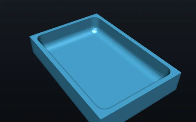
The DFM design loop closes its own findings
Parts that break a machining, moulding, sheet or print rule come back fixed from the checker's own advice.
8 of 8 parts fixed PCB certification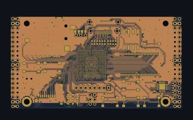
Pass PCB qualification before you build
One run over your board gives a UL and IPC readiness report, with the one change that fixes each finding.
5 checks pass · 1 fail PCB analysis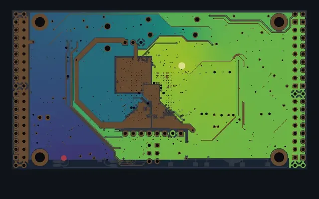
Your board, analysed before it is built
IR drop, impedance, weave skew, eye diagrams and via life, read straight from your board file.
Eyes open at 56 Gbps Drawings to STEP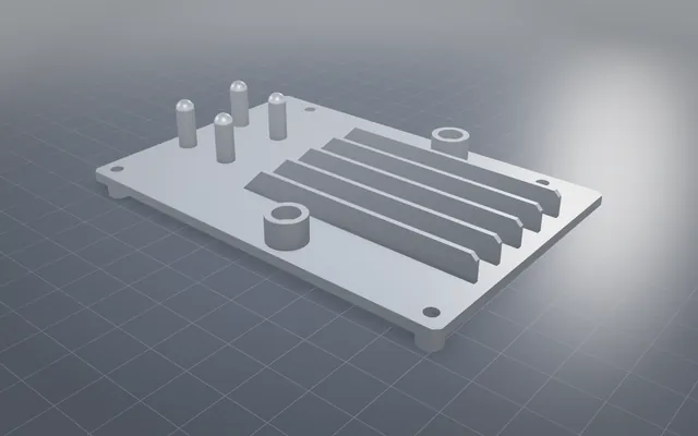
Manufacturing drawings in, STEP out, checked against the original
Real manufacturing drawings become exact 3D models, each matched against the official model.
6 of 6 NIST parts matchedBuild your own part with NativeCAD
Free for education and makers with a registered key · $200 per seat per year · Kernel SDK for products.