A hydrogen fuel-cell precooler, printed as one piece
A fuel cell's air compressor delivers air at 170 °C, and the stack wants it at 80 °C or below. This one-piece printed aluminium exchanger is designed to do that cooling in a straight run of duct. Inside, 267 coolant tubes are wound in seven counter-rotating layers and fed from a hub with two plenums. NativeCAD generated it from a written brief, checked it four ways (thermal, structural, vibration and printability), then ran a virtual first article and re-ran the whole design for a 50 kW and a 200 kW stack.
All of the air through the tubes
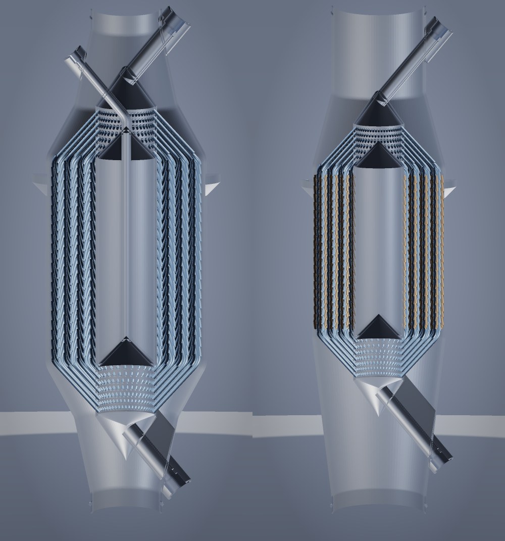
The first build of this core left the air an easy way round: straight, open channels between the tube layers that ran the full length of the core. Most of the flow took them. The redesign closes every one of those channels and opens the inlet up, so the whole air stream now has to work its way through the tube bundle, and the exchanger finally does the job it was sized for.
The inlet now opens at a gentle 7° with a throat as large as the core's own open area, so the flow reaches the outer rows instead of shooting down the middle. At the top, the coolant feed crosses the outlet stream as a single pipe, with no separate bleed line beside it. Air-side pressure drop is 968 Pa, 0.39 % of the line pressure. The same rules re-ran every size:
| Size | Air through the tubes | Heat rejected | Air out | Air pressure drop |
|---|---|---|---|---|
| HX-050 | 12 % → 97 % | 3.4 → 5.1 kW (+50 %) | 109 → 77 °C | 819 Pa |
| HX-100 | 13 % → 97 % | 7.3 → 10.3 kW (+41 %) | 104 → 77 °C | 968 Pa |
| HX-200 | 13 % → 97 % | 16.3 → 21.3 kW (+31 %) | 97 → 74 °C | 928 Pa |
finish-machined faces
section through the metal
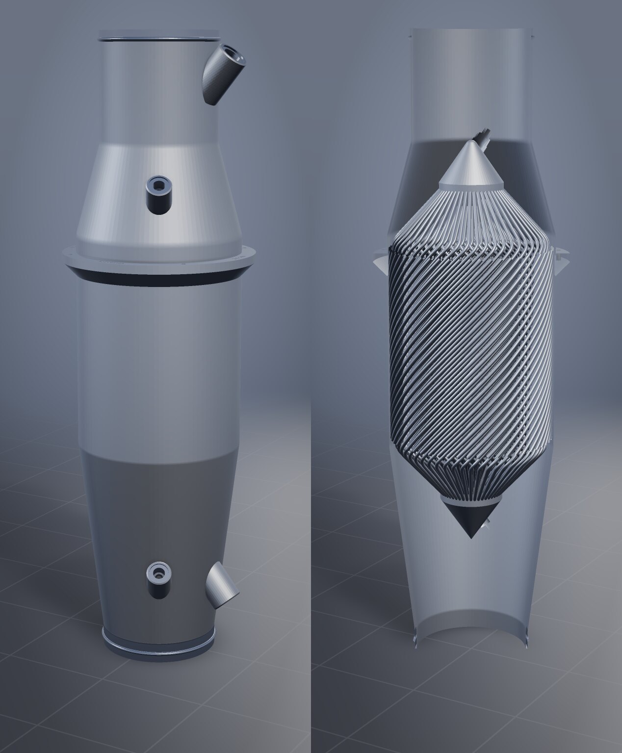
Drag to orbit, scroll to zoom. Air rises through the duct; coolant flows down the tubes, against the air. The bright faces are the ones machined after printing: the collar's mounting face with its engraved marking, the hose stubs and the port seats. Switch to Coolant temperature or Layers to see the 1,505 printed bridge nodes that tie the layers into one stiff weave.
The job
A ~100 kW PEM fuel-cell module breathes about 109 g of air a second. Its compressor raises that air to 2.5 bar, and in doing so heats it to around 170 °C. The membrane would dry out at that temperature, so a charge-air cooler sits between the compressor and the humidifier. It has to dump about 10 kW into the low-temperature coolant loop (50/50 ethylene-glycol / water, 20 L/min at 55 °C) without taking much pressure out of the air, because every pascal lost has to be made up at the compressor.
Fuel-cell trucks, buses and hydrogen aircraft all need this part. It also has to be small and light, because it shares the engine bay with the stack, the humidifier and the hydrogen system.
Why it can only be printed
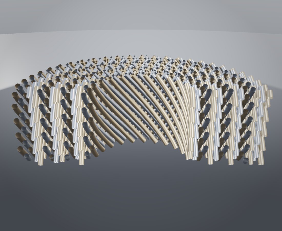
- Seven layers of tubes, wound in alternating directions. The layers alternate hand at 47° to the horizontal, so neighbouring layers cross at right angles and the air never meets a straight row of tubes to slip through. Winding this by hand is how cryogenic coil-wound exchangers are made, one tube at a time. Here it is a single print.
- Every tube turns into the hub on its own path. At each end, every tube bends from its helix into a 47° funnel and lands in the hub's plenum. The 7 layers' funnels are nested cones, so no tube crosses another. The tightest gap between neighbours is 0.41 mm, right at the hub.
- Nothing overhangs. The air flows up the print direction. Every tube, the duct's diffuser and nozzle, the hub's cones and both coolant pipes stand at 47° or steeper, so the bundle prints without supports. The only supports on the whole part sit under the two coolant-port bosses, outside the duct, where they are easy to reach.
- The joints are part of the metal. 1,505 short bridge nodes join neighbouring layers where they cross, and the tubes grow into the hub with a blended fillet. There are no brazed joints to leak.
How it was made in NativeCAD
The brief was the duty above plus a few rules: inline duct, counter-flow, all-printable, mounting on a bolted collar. From that brief, NativeCAD's agent wrote a parametric generator and built the part as exact geometry through the same operations its MCP server exposes:
- The duct is one revolved wall. It runs from a Ø62 mm hose stub, through a two-stage diffuser and an Ø144 mm core, to a matching nozzle and outlet stub. It carries hose beads at both ends, rounded on the clamp side and 45° underneath so they print without support, and a 45°-chamfered mounting collar with four M5 tapped holes on a Ø160 mm circle, and the part number, alloy and serial are engraved into the collar's face. Every corner of the wall profile is rounded with an 18 mm knuckle; the structural section below shows why.
- The fittings are standard ones a technician already has tools for. The coolant pipes end in round bosses with M18×1.5 straight-thread O-ring ports (ISO 6149 style): a spot-faced seat, a thread counterbore and the coolant bore. Two round Ø22 mm bosses with M12×1.5 ports, angled at 45° off the diffuser and the nozzle, take air temperature and pressure sensors before and after the core. The 45° is for the printer: a boss at that angle builds without support, and it points the probe into the air stream. On a machined or welded duct you would fit a radial boss instead. Each boss's root runs back into the wall far enough to bury the whole rim of its foot. That is about 17 mm for the inlet boss, which stands on the diffuser cone almost 60° off square, so its foot grows out of the wall like the coolant ports' instead of standing off it.
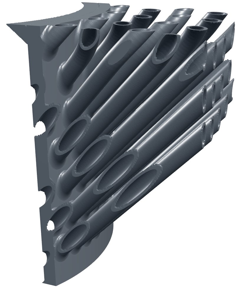
- The joints are filleted, as printed. Where a coolant pipe leaves the hub or passes through the duct wall, and where a port or sensor boss grows out of the wall, the printed part has a fillet. The exact model keeps those bodies separate, so the viewer draws each fillet from the fused print geometry (NativeCAD's implicit field engine) over the joint. The same goes for the holes: where a tube or pipe bore crosses the hub wall, or a pipe or sensor bore crosses the duct wall, the exact bodies stay whole and the viewer opens the bore.
- The hub is one revolved shell with three chambers. Each plenum is only as tall as the band where its tubes come in. Between the plenums, two 45° bulkheads close off a dry chamber. It is open to the air side through 4 Ø3 mm vents that fall at 60° from a narrow flat bench round its floor, so condensate and loose powder run out of it; they are all at one height, so no air flows through it. Coolant enters the top of the downstream plenum, runs down the tubes against the rising air, and leaves from the very bottom of the upstream plenum, the point of a funnel that opens straight into the outlet pipe. The inlet and outlet pipes run through the duct wall at 50° into round port bosses grown from the wall. Where the outlet pipe crosses the diffuser, upstream of the core, it is faired: a swept teardrop whose tail runs two pipe diameters downstream, buried in the hub and duct walls at both ends. A bare Ø16 mm pipe there would trail its wake across the core face; at this Reynolds number (about 15,000) a fairing of that shape has roughly a tenth of a cylinder's drag and a far narrower wake. Every face of it looks up or sideways, so it prints without support. The inlet pipe crosses the nozzle, downstream of the core, so it stays bare. It crosses the axis just under the tip of the hub's 35° tail cone, so the tail ends in a rounded tip level with the top of the pipe and runs straight into it, rather than leaving a few millimetres of point standing proud.
- The 267 tubes are swept along their own paths with
cad_tube_sweep, Ø3.0 mm outside and Ø2.2 mm bore. Each one checked watertight, 299.8 cm³ in total, within 0.11 % of the exact swept volume. The tightest bend radius is 13.6 mm. - The fused print geometry comes from NativeCAD's implicit field engine. The B-rep keeps each tube exact; the printer needs one fused solid, with fillets where the tubes meet the hub, bores open into the plenums and bridge nodes merged into the weave. The two cut-aways below are that field, contoured at 0.15 mm.
Flow check: does the coolant get through?
Yes, in the file you download and in the part a printer would build. Installed as printed, with the air rising, coolant enters the top of the downstream plenum, runs down all 267 tubes against the air and leaves through the funnel at the bottom of the upstream plenum, so the circuit drains dry. There is no bleed line, so the loop is vacuum-filled: otherwise about 18 mL of air stays under the upstream plenum's roof on first fill.
Two rules check that on the whole part. FLOW-CONNECT floods the void from the inlet and lists every tube the flood does not fill end to end. FLOW-TRAP finds every pocket where gas cannot rise to a vent or liquid cannot fall to a drain. Both ran on all three sizes, two ways.
The shipped STEP. Each download below is one exact model with every passage the fluids use cut by the kernel: every tube with its own bore, every tube root through the hub wall, both coolant pipes through the hub and the duct, the sensor ports, the bleed line and the dry chamber's vents. The bridge nodes and fittings are in it too: each node rod's ends are cut by planes parallel to its tubes, just outside their bores, and where a tube's root leaves the hub under the outlet fairing's root the fairing's tail tip is cut back. Bodies overlap where the printer fuses them, and no hole is wider than the bore it serves. The kernel imported each file and tested point-in-solid along both pipe bores, through both roots of every tube, along the bleed line and through each vent, and round the bore at both ends of every bridge-node rod and wherever a tube runs past the outlet fairing.
The fused print geometry. This is the one-piece part as a printer builds it: tubes blended into the hub, bores opened into the plenums, pipes run through the walls into the port seats. It is the same signed-distance field the virtual CT uses, sampled over the whole part on one 0.5 mm voxel grid.
| HX-050 | HX-100 | HX-200 | |
|---|---|---|---|
| Shipped STEP: coolant in reaches coolant out | yes | yes | yes |
| Tubes carrying flow | 145 of 145 | 267 of 267 | 547 of 547 |
| Coolant inlet bore / outlet bore | open / open | open / open | open / open |
| Air bleed line, roof to port | none | none | open |
| Dry-chamber vents open | 4 of 4 | 4 of 4 | 4 of 4 |
| Bridge-node rod ends clear of their bores | all 1,498 | all 3,010 | all 6,608 |
| Tube bores past the outlet fairing | clear | clear | clear |
| Bodies in the file | 1,215 | 2,341 | 4,992 |
| Fused print geometry: coolant connected | yes | yes | yes |
| Tubes carrying flow | 145 of 145 | 267 of 267 | 547 of 547 |
| Wetted volume cut off | 0.0 mL | 0.0 mL | 0.0 mL |
| Coolant-to-air contact with no wall | none | none | none |
| Gas trapped / liquid trapped | 8.63 / 0.00 mL | 18.84 / 0.00 mL | 60.74 / 0.00 mL |
| Narrowest throat (radius): tube / pipe | 1.07 / 2.15 mm | 1.05 / 2.00 mm | 1.01 / 2.00 mm |
| Coolant verdict | pass | pass | pass |
| Air: inlet face reaches outlet face | yes | yes | yes |
| Air side sealed off | 0 mL | 0 mL | 0 mL |
| Condensate trapped | 0.000 mL | 0.000 mL | 0.000 mL |
| Air verdict | pass | pass | pass |
At 0.5 mm a pocket one voxel deep cannot be told from the staircase on a sloping wall. Those pockets are not counted (at most 0.05 mL per size). The throats come from the exact field along each centreline. The air throat is only resolved to one voxel. The check catches what it is meant to catch: with tubes 0 and 100 plugged at mid-length (HX-050), it fails with exactly t0_0 and t3_27 (143 of 145 live).
What changed. The first time this check ran, the downloads failed it: the files held no tubes, the hub and duct walls were whole across both coolant pipes, the hub's dry chamber was sealed (224, 388, 859 mL across the three sizes, and a sealed pocket in a printed part fills with powder), and the HX-200 outlet's thread counterbore started 1.0 mm inside the duct's inner skin, where coolant would have met the air with no metal between. The files now carry every cut. The dry chamber has 4 Ø3 mm vents that fall at 60° from its floor, so it drains and can be cleared of powder. Both coolant port bosses stand up to 3.6 mm further out along their pipes, so every thread counterbore keeps at least 1.6 mm of metal to the air passage.
Thermal and pressure
The exchanger was rated as built. The geometry gives the tube area (0.84 m²), the free flow area at every height and each layer's coil radius. That rating is then marched in 200 steps along the part in counter-flow. The air side is treated as an inclined staggered tube bank (Zukauskas, with a 45° yaw correction). The coolant side is laminar flow in a helical coil (Manlapaz–Churchill, Dean number from each layer's helix). Fouling allowances are included on both sides.
The coolant path
An earlier version of the hub had one bulkhead. Its inlet plenum ran the full length of the core, but the tubes only take coolant from the top of it. That left 647 mL of coolant in the hub, most of it a dead column under the tube entries, with nothing to sweep out air or debris. Now each plenum covers only its band of tube entries and the hub holds 217 mL. The whole part holds 0.57 L where it held 1.00 L.
Installed as printed, with the air rising, the coolant falls through the part from top to bottom. It comes in at the top of the downstream plenum, where the inlet bore's top edge is the plenum's apex, so air entering with it is carried straight down the tubes. The upstream plenum is pointed at both ends: a 45° roof over the tube entries and a funnel under them whose point is the mouth of the outlet pipe.
So the part drains itself dry. The lowest point of the whole coolant circuit sits inside the outlet bore, and not a drop is left below it: coolant, flushing water and loose powder all run down the funnel and out. The outlet pipe leaves from the solid tip of the hub's nose and falls all the way to its port, clear of every other wall.
There is no air bleed. An earlier version ran a Ø6 mm bleed line from the top of the upstream plenum's roof up the hub's axis and out to a plugged port on the duct. It put a pipe through the middle of the hub and a second pipe across the outlet stream. Without it the hub is three chambers end to end and nothing runs through the middle: plenum, a hollow dry chamber (its four Ø3 mm vents let loose powder out after printing), plenum. The cost is first fill. Installed, the upstream plenum's roof is the highest point of the circuit and holds about 18 mL of air with nowhere to go, so the loop is vacuum-filled, or filled from a degas bottle mounted above the part.
The tubes are not all the same length: the inner layer's run 274 mm and the outer layer's 377 mm. With one bore throughout, the short inner tubes would take more than their share. The flow split, solved with every layer at the same pressure drop, would run from 1.09× to 0.94× the mean. So each layer gets its own bore, from Ø2.10 mm inside to Ø2.20 mm outside, and the split comes in within 0.5 %. The heat duty hardly moves, because the tighter coils on the inside already offset most of the length difference. What the grading buys is the same coolant velocity in every tube, so no layer runs slow enough to foul or hold air. It costs 123 Pa of coolant pressure drop. A printed bore that comes out 0.05 mm off nominal changes that tube's flow by about 10 %. That scatter is random from tube to tube and averages out across the bundle; the length bias, which the grading removes, does not.
| Layer | 1 | 2 | 3 | 4 | 5 | 6 | 7 |
|---|---|---|---|---|---|---|---|
| Bore, mm | 2.10 | 2.11 | 2.13 | 2.15 | 2.17 | 2.18 | 2.20 |
| Flow, one bore | 1.09 | 1.06 | 1.04 | 1.01 | 0.98 | 0.96 | 0.94 |
| Flow, graded | 1.01 | 0.99 | 1.00 | 1.00 | 1.00 | 1.00 | 1.00 |
Across the operating range (coolant at 20 L/min)
| Air flow | Heat removed | Air out | Air pressure drop |
|---|---|---|---|
| 30 % | 3.7 kW | 59.3 °C | 91 Pa |
| 50 % | 5.8 kW | 64.9 °C | 234 Pa |
| 70 % | 7.8 kW | 69.8 °C | 444 Pa |
| 85 % | 9.1 kW | 73.2 °C | 645 Pa |
| 100 % | 10.3 kW | 76.3 °C | 885 Pa |
| 115 % | 11.5 kW | 79.3 °C | 1163 Pa |
| 130 % | 12.6 kW | 82.0 °C | 1480 Pa |
Pressure: the knuckle that cut the stress by nine
CalculiX solved the duct at proof pressure (2.25 bar gauge, 1.5 × the working air pressure) with the collar bolted down. The first version had sharp cone-to-cylinder corners, and the peak stress sat on the diffuser's corner at 99.8 MPa, a safety factor of only 1.75 on yield. Rounding every corner of the wall profile with an 18 mm knuckle brought the peak down to 11.6 MPa. That is the plain hoop stress of a 144 mm tube with a 1.6 mm wall, which is exactly what the solver should find once the corners stop concentrating load.
The hub's two plenums were solved at 4.5 bar gauge, 1.5 × a 3 bar coolant loop, with no help from the air pressure outside. The dry chamber between them is vented, so each bulkhead carries that pressure on one face. The peak there is 10.2 MPa, a safety factor of 17. The tubes themselves carry a hoop stress of about 1 MPa at that pressure. Material allowable is stress-relieved LPBF AlSi10Mg at a 175 MPa yield. Meshes are quadratic tetrahedra: 39,775 nodes on the duct and 249,959 on the hub.
Vibration: why the layers are tied together
A loose tube is a problem. CalculiX puts the first mode of the longest tube (377 mm long, clamped at both plenums, carrying its coolant) at 90.4 Hz. The speed at which flowing air starts to drive a tube that soft (Connors' criterion, with a log decrement of 0.03) is about 3.6 m/s. The air between the tubes moves at about 7.4 m/s, so an untied bundle would be unstable.
So the design ties the layers to each other. On 7 rings along the core, every tube is bridged to its neighbour in the next layer at the point where they cross: 1,505 Ø2 mm nodes in all. A frame model of the whole bundle (every tube a beam; its single-tube result is within 9 % of CalculiX) puts the tied bundle's first mode at 532 Hz. A CalculiX beam model of the same bundle, which lets the short bridges shear, puts it at 407 Hz. Taking the lower figure, the instability threshold rises to 16.3 m/s, 2.2 × the mean gap velocity.
The bundle's first modes, from 407 Hz up, sit well above the road and airframe vibration bands. They do overlap the band where vortices shed off the tubes at full flow. The vibration survey below works out what that does to the tubes, ahead of the accelerometer.
Print checks
| Body | Metal powder-bed (DMLS) rules | Notes |
|---|---|---|
| Duct, collar, stubs | approved, no findings | thinnest wall 1.60 mm; steepest overhang 45.0° from vertical |
| Hub plenums | approved, no findings | thinnest wall 2.00 mm; the two bulkheads and every cone over a chamber is 45° or steeper; the drain funnel looks up |
| Coolant pipes | approved | barrels pass; only the outlet hose end face flags (50° past vertical), and that face is machined after printing |
| Outlet fairing | approved on the fused part; the standalone body's trimmed ends flag | no overhang faces, steepest 39.6° from vertical. Its thinnest wall, 0.88 mm, is where the trim leaves a knife edge 0.8 mm inside the hub and duct walls, which the print fills |
| Coolant port bosses | approved on the fused part; the standalone body's trimmed foot flags | round bosses grown from the duct wall. The standalone boss bodies are trimmed flush with the wall, and the wall probe flags the knife edge at that trimmed foot (0.28 mm); in the printed part the foot is fused into the 1.6 mm duct wall under the fillet, and the virtual CT of the fused part puts the thinnest metal around the outlet pipe and its boss at 1.4 mm. Both bosses take light supports under their 40° undersides, and the seats are machined afterwards |
| Sensor bosses | approved on the fused part; the standalone body's trimmed foot flags | round bosses at 45°, trimmed flush with the duct's inner wall; the wall probe flags the knife edge where the standalone body meets the wall (0.52 mm), which the print buries in the 1.6 mm wall under the fillet; sides and faced ends at 63° |
| Tubes | thin-wall process | the 0.4 mm walls are below the generic 0.8 mm handling floor and pass on a thin-wall parameter set (0.3 mm floor, measured 0.35 mm); no barrel surface overhangs; the end caps sit inside the plenum and are not printed surfaces |
- Build: inlet down, air-flow axis vertical, 172 × 172 × 472 mm. That needs a large-format powder-bed machine with at least 472 mm of Z.
- Powder out: every cavity is open. The plenums drain through the two coolant pipes and every bore runs plenum to plenum, so the coolant circuit can be flushed end to end. The dry chamber empties through its 4 vents, which sit at the bottom of the chamber as printed and rise outward at 45°.
- Post-print: stress-relieve and remove the port-boss supports; flush and pressure-test the coolant circuit; face the collar and the hose ends; tap the four M5 collar holes; and finish the port seats and threads (M18×1.5 and M12×1.5).
The first article, run on a computer first
A buyer signs off a first article on five checks: a helium leak test, a proof and burst test of the coolant circuit, a hot-air rig run at the design point, an accelerometer survey across the flow range, and CT of the tube roots. Each has a counterpart that runs on the same geometry before any metal is printed. None of them replaces the physical test. What they do is say what each test should find, so the first article is judged against a window instead of a single number.
| Physical check | What ran here | Result | The first article passes if |
|---|---|---|---|
| Helium leak | Virtual CT of the fused print geometry at every place the coolant and the air meet (below) | 0 leak paths in 21 windows; thinnest coolant-to-air wall 0.38 mm, 3 laser tracks | the circuit is tight; a leak found here is print porosity, not geometry |
| Proof and burst | Elastic-plastic, large-deflection CalculiX solve of the coolant plenum, pressure ramped until it collapses | collapse at 212 bar, 47 × the 4.5 bar proof; 106 bar counting every tube hole as open | no permanent set at 4.5 bar; a burst sample holds past 100 bar |
| Hot-air rig | The rating model on clean surfaces, an independent second correlation and 250 Monte Carlo runs over every uncertainty | 10.56 kW and 882 Pa expected on a clean part | heat duty 9.4–11.3 kW, air pressure drop 761–1,179 Pa |
| Accelerometer survey | 311 bundle modes against vortex shedding, buffeting, acoustic resonance and fluid-elastic instability, 20–130 % flow | first mode 407 Hz; instability margin 2.07× at design flow; resonant response at most 63 µm (bound) | the first bundle mode reads 407–532 Hz and no peak grows with flow |
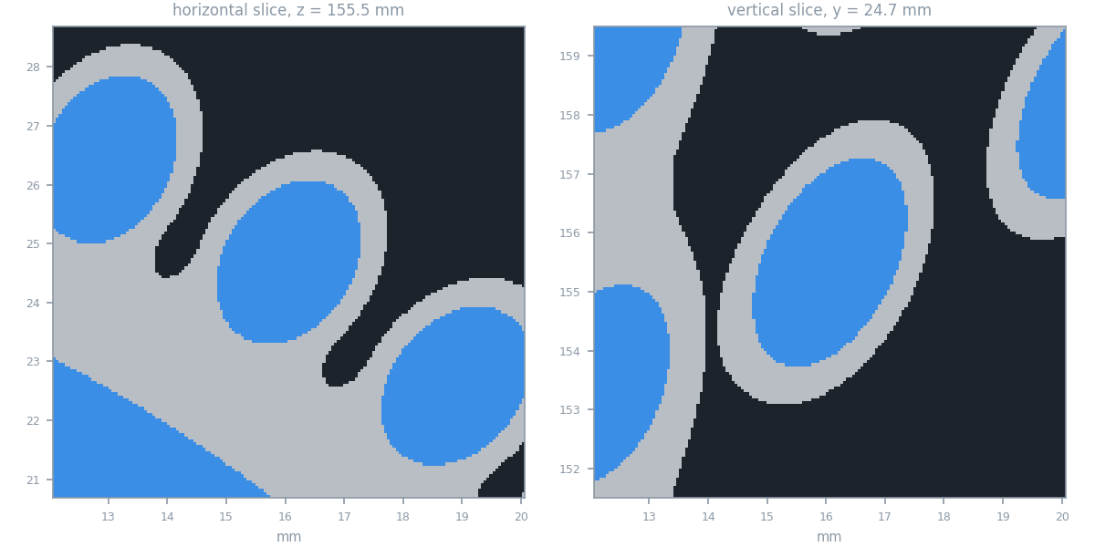
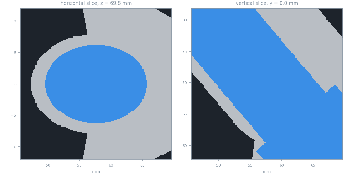
| CT of the tube roots | 14 worst-case tube roots and 4 pipe joints, sampled at 0.05 mm voxels | every bore open, roots filleted, 0 trapped powder pockets | the scan matches the slices below |
Leak paths and CT: the print file, scanned before it exists
The printer builds one fused solid, so that is what gets scanned. NativeCAD's implicit field engine evaluates the whole part (tubes blended into the hub, bores opened into the plenums, bridge nodes merged, coolant pipes through the duct wall) on a voxel grid in a window around each joint, and every voxel is labelled metal, air side or coolant side. The windows are the root of the tube in each layer whose lead runs closest to its neighbours, at both ends, plus both coolant pipes where they pass through the hub wall and the duct wall. Then the scan is read the way CT software reads one:
- Leak paths: 0. No connected void anywhere holds both coolant-side and air-side voxels.
- Trapped powder: 0. No void is sealed off from both circuits, so every grain of powder has a way out.
- Wall: the thinnest metal between coolant and air is 0.38 mm (the nominal 0.4 mm tube wall, to within a voxel), at least 3 laser tracks thick. At the pipes it is 1.42 mm.
- Roots: in the outer layer, neighbouring tubes come within 0.38 mm of each other as they reach the hub. The printed fillet fuses them into a web there, and the scan shows it leaves no closed pocket behind.
Proof and burst
CalculiX solved the coolant plenum with the alloy's full stress-strain curve (stress-relieved LPBF AlSi10Mg: 175 MPa yield, 280 MPa ultimate) and large-deflection geometry. The pressure was stepped up until the solver could no longer find equilibrium, which is the load at which the plenum collapses. First yield appears at about 77 bar; collapse comes at 212 bar. The solved body has no tube holes in its wall. Taking every hole as open, with no credit for the tubes and fillets that close them (a ligament efficiency of 0.50 across the tube-entry bands), still leaves 106 bar, 23 × proof. The tubes themselves (thinnest wall from the CT) would hold about 707 bar and the coolant pipes about 498 bar, so the hub is the weakest point by a wide margin.
The rig window
A rig tests a clean part, so the prediction drops the fouling allowance the design rating carries: 10.56 kW and 882 Pa at the design point (109 g/s of air at 2.5 bar and 170 °C in; 20 L/min of coolant at 55 °C). As an independent check, the same exchanger was rated with a second tube-bank correlation (VDI Heat Atlas, Gnielinski), which comes out 7.4 % lower at 9.77 kW. The window below comes from 250 runs that sample both correlations and every other uncertainty: air- and coolant-side heat transfer, friction, the roughness of as-printed tube surfaces, and the rig's own instruments.
If the first article reads near the bottom of the window, the geometry follows the more conservative correlation. Then the outlet would sit just above 80 °C once fouled, and the fix is a re-run with the core 23 mm longer, which brings it back under 80 °C on that correlation too.
The vibration survey, in advance
Two models of the tied bundle disagree. The frame model above puts the first mode at 532 Hz. A CalculiX beam model of the same 267 tubes and 1,505 nodes puts it at 407 Hz, because it lets the short bridge ligaments shear. Both treat each bridge as a Ø2 mm rod from tube centre to tube centre, which is softer than the real fused joint, so the true value should sit at or above the lower figure. Every margin here uses 407 Hz.
- Fluid-elastic instability (Connors): the threshold is 2.07× the gap velocity at design flow at the hot inlet, where the air is fastest, falling to 1.59× at 130 % flow.
- Vortex shedding sweeps the bundle modes from about half flow upward; at full flow 553–1,383 Hz covers dozens of them. Even with every tube driven in phase with the mode at the largest lift coefficient TEMA tabulates for tube arrays (CL 0.09), which is an upper bound, the worst resonance at design flow moves a tube 63 µm (2.1 % of its diameter, just over TEMA's 2 % guideline on this upper bound; the mode doing it is at 715 Hz, and the survey below checks it first) and puts 7.4 MPa of bending stress in it. At 130 % flow that grows to 107 µm and 12.4 MPa, still well under the 40 MPa we allow an as-printed surface over 107 cycles.
- Turbulent buffeting peaks at 323 Hz at design flow (Owen), and TEMA's force coefficient is zero for modes above 88 Hz, so it cannot drive this bundle.
- Acoustic resonance: the first circumferential mode of the annulus, with its sound speed lowered by the 17 % tube solidity, sits at 1,244 Hz at the hot end and 1,105 Hz at the cold end. Shedding reaches it above 75 % flow. Chen's parameter peaks at 1,773, under the 2,000 below which tube-array resonance is not expected.
That gives the survey its plan: an accelerometer on the collar and one on each port boss, a microphone in the inlet stub, and a slow sweep from 20 % to 130 % flow. Check the first bundle mode against 407–532 Hz, and check that no peak tracks flow and grows. Watch the 715 Hz mode at design flow, the one with the largest shedding bound. Listen for a tone near 1,244 Hz above three-quarter flow.
Re-run, not redesign
Stack size, line pressure, inlet temperature and the coolant loop are inputs. From them the generator derives the rest: the number of layers, the hub (just large enough for the outer layer's tubes to land side by side), the duct, the inlet stubs, the pipe bore and port thread, the collar and the bolt circle. Here it is re-run, untouched, for a 50 kW and a 200 kW stack. Every tube was swept and checked again, and every check on this page ran again. Pick a size in the viewer above to see each one.
| HX-050 | HX-100 | HX-200 | |
|---|---|---|---|
| Stack | 50 kW | 100 kW | 200 kW |
| Air, coolant | 55 g/s, 10 L/min | 109 g/s, 20 L/min | 218 g/s, 40 L/min |
| Tubes | 145 in 5 layers, 46 m | 267 in 7 layers, 89 m | 547 in 10 layers, 199 m |
| Envelope | 136 × 136 × 496 mm | 172 × 172 × 572 mm | 233 × 233 × 708 mm |
| Mass, dry | 2.44 kg | 4.06 kg | 7.94 kg |
| Coolant ports | M14×1.5 | M18×1.5 | M22×1.5 |
| Coolant in the hub, before / now | 344 / 93 mL | 647 / 217 mL | 1,655 / 689 mL |
| Tube bores, inner to outer layer | Ø2.14–2.20 mm | Ø2.10–2.20 mm | Ø2.03–2.20 mm |
| Flow split, one bore / graded | ±4 % / ±0.5 % | ±8 % / ±0.5 % | ±13 % / ±0.6 % |
| Heat removed | 5.1 kW | 10.3 kW | 21.3 kW |
| Air out | 77.1 °C | 76.5 °C | 73.8 °C |
| Air / coolant pressure drop | 818 Pa / 12.4 kPa | 968 Pa / 13.4 kPa | 928 Pa / 14.0 kPa |
| Rig window | 4.6–5.7 kW | 9.4–11.3 kW | 19.4–22.8 kW |
| Proof safety factor, hub / duct | 25.2 / 21.3 | 17.1 / 15.1 | 10.3 / 7.4 |
| Hub collapse | 285 bar | 212 bar | 124 bar |
| Bundle first mode | 453 Hz | 407 Hz | 374 Hz† |
| Instability margin, design flow | 2.41× | 2.07× | 2.04׆ |
| Metal-print rules | approved | approved | approved |
The re-run also caught something. The HX-200's tubes run longer leads into a larger hub, and with the core's seven bridge rings alone its first bundle mode dropped to 327 Hz (CalculiX), an instability margin of 1.79× at design flow, under the 2× the HX-100 holds. Ten core rings instead of seven only lifted it to 348 Hz (1.90×), because the soft part was the funnel leads, not the core. So the generator now ties the leads in the funnel: at 2 heights in each funnel every tube is bridged to the layer outside it and to its neighbour in the same layer, 2,692 more Ø2 mm ligaments (about 0.07 kg), and the neighbour ties close each layer into a ring. With them the HX-200's first bundle mode is 374 Hz†, a margin of 2.04× at design flow, above the 2× the HX-100 holds.
† How these two HX-200 figures were found: CalculiX was not available where the tied bundle was solved, so it went through a calibrated frame model instead (the same 547 tubes, graded bores and coolant mass; the bridge ligaments' stiffness set so the HX-100 reproduces its CalculiX 407 Hz). On the HX-200's two untied bundles it lands 4 to 5 % below CalculiX, so the figure errs low; scaled by the model's tied-to-untied ratio, CalculiX would put it near 391 Hz (2.14×). The ties are in the HX-200 bridge-node file the generator reads. The HX-200 STEP, its viewer model and the connectivity checks above describe the bundle with the core rings only; they do not include the funnel ties.
More demos
All demos →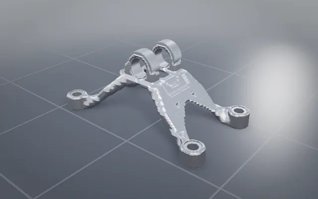
The GE jet engine bracket, lighter and carrying every load
The classic titanium bracket optimised and offered to print, cast, machine or weld, with STEP to download.
83.6% lighter Printed pendant
A planetary gearbox you can wear, printed in one piece
A working gearbox pendant that comes off a desktop printer already assembled and turning, in two colours.
5 moving parts, one print Implicit vs explicit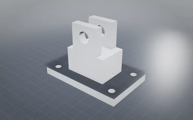
Implicit where it breathes, exact where it bolts
Lattices and graded cores on the same body as true bolt holes, with STEP, drawings, analysis and print prep.
FEA loop
Finite-element analysis your agent can run
Stress and vibration results from the same AI session that built the part, with the peak and its margin.
6 designs solved in FEABuild your own part with NativeCAD
Try it free with the keyless evaluation · $200 per seat per year · Kernel SDK for products.