A printed gyroid heat exchanger that meets its duty
A charge-air cooler for an 8–10 kW fuel-cell stack: 118 °C air in, 61.3 °C out, against 65 °C allowed. It removes 515 W where the duty asks for 482 W, in a 114 × 106 × 62 mm package that bolts to its plumbing through four exact flanges.
Two fluids, one wall
Air runs through the core in one direction and coolant across it in another, each in its own connected network, separated by a 0.82 mm wall. Every path from the air ports stays in the air network and every path from the coolant ports stays in the coolant network: 0 places where the two meet. Each network is one connected, watertight passage with a 1.1 mm narrowest throat, wide enough to clear the powder.
Drag to orbit, pinch or scroll to zoom.
Every triangle of the printed metal is here, 2.5 million of them, not a simplified preview. Section the core to see the two passages wound through each other, split by a 0.82 mm wall.
Mid-plane section of the 56 mm core. Switch a fluid off to follow the other network on its own.
Rated to the duty
| Result | Requirement | |
|---|---|---|
| Heat removed | 515 W | 482 W |
| Air out | 61.3 °C | ≤ 65 °C |
| Air-side pressure drop | 2.7 kPa | ≤ 5.0 kPa |
| Coolant-side pressure drop | 0.40 kPa | ≤ 20 kPa |
| Effectiveness | 0.90 | – |
| Wall thickness | 0.82 mm | ≥ 0.8 mm |
| Wall stress at 0.23 MPa proof pressure | 4.0 MPa | yield 230 MPa |
Air 9.0 g/s at 200 kPa, 118 °C in. 50/50 glycol-water coolant at 3.0 L/min, 55 °C in and 57.8 °C out.
Flanges that bolt on
Four SAE J518 Code 61 split-flange ports, modelled as exact faces and cylinders: SAE J518 Code 61 3/4" (-12) on the air side, SAE J518 Code 61 1/2" (-08) on the coolant side. Bolt holes, port bores and sealing faces are true geometry in the STEP, and the drawing carries every callout.
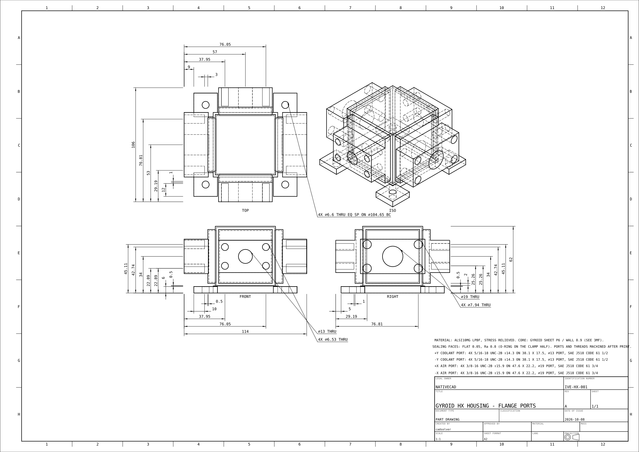
| Port | Fluid | Flange |
|---|---|---|
| -x | air | 4X 3/8-16 UNC-2B ↧15.9 ON 47.6 X 22.2, ⌀19 PORT, SAE J518 CODE 61 3/4 |
| +x | air | 4X 3/8-16 UNC-2B ↧15.9 ON 47.6 X 22.2, ⌀19 PORT, SAE J518 CODE 61 3/4 |
| -y | coolant | 4X 5/16-18 UNC-2B ↧14.3 ON 38.1 X 17.5, ⌀13 PORT, SAE J518 CODE 61 1/2 |
| +y | coolant | 4X 5/16-18 UNC-2B ↧14.3 ON 38.1 X 17.5, ⌀13 PORT, SAE J518 CODE 61 1/2 |
Ready for the printer
Every wall sits above the 0.8 mm floor and every passage is open to clear its powder. Stood corner-up, only 10.7 % of the surface is steeper than 45°, and nothing inside the networks needs a support. After printing: face the four sealing surfaces, tap the 16 bolt holes, ream the ports.
Downloads
More demos
All demos →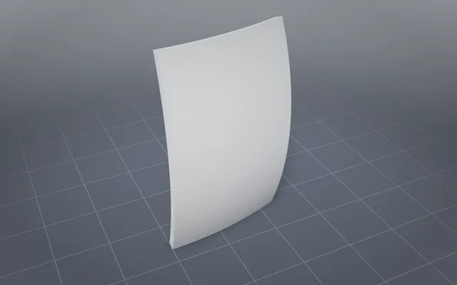
A curved skin panel whose lattice follows the skin
A doubly curved nacelle panel with exact skins, countersunk fastener holes and a lattice that never clips.
4.4× lower peak strut stress Metal print prep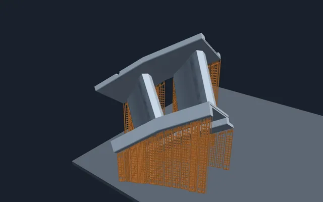
A turbine vane ready for the metal printer in under two minutes
Orientation, supports and a full build plate chosen automatically, then graded by an independent checker.
94.8% of overhangs held up 3D nesting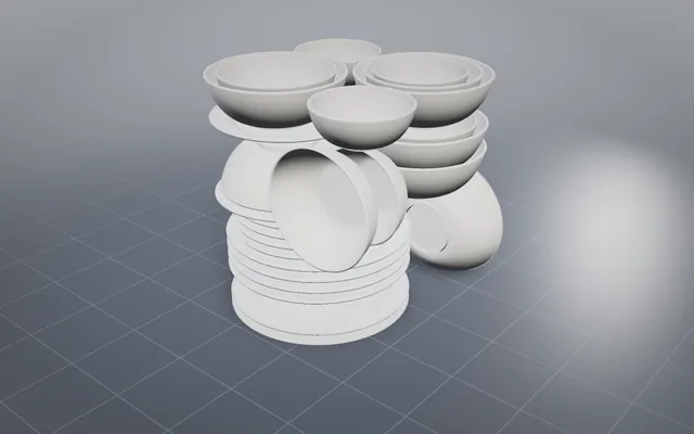
A whole dinner service nested in one SLS build
Bowls inside bowls and plates under plates, every gap proved on the real triangles before the build starts.
30 pieces, one SLS build FEA loop
Finite-element analysis your agent can run
Stress and vibration results from the same AI session that built the part, with the peak and its margin.
6 designs solved in FEABuild your own part with NativeCAD
Free for education and makers with a registered key · $200 per seat per year · Kernel SDK for products.