Qualification report · NASA Rotor 67 fan blade · NativeCAD
NASA Rotor 67 — blade qualification report
NASA Rotor 67, a transonic FAN rotor (a compressor), rebuilt from NASA TP-1493/TP-2879 — not a turbine. Four checks, one verdict, every number read from the run that produced it (calculix 2.21).
The verdict is forced only by what the TP-1493 stage has: its 34-vane stator downstream (EO 34) and that order's second harmonic (EO 68, an upper bound). Its lowest safety factor is 1.19, at Mode 19 × EO 34 at 17395.5 rpm; across the declared bands (root Kt, forcing amplitude, damping) that crossing runs from 0.74 at the worst corner to 1.62 at the favourable end of one band. 4 of 10 in-band stage crossings are below 1.5 at the quoted inputs, 2 of them set by the steady root stress (the Langer yield line on a Kt-peak mean) rather than by vibration; every one of them clears it at the favourable end of at least one band. Installed behind a 2/rev inlet distortion, a scenario neither NASA rig had, Mode 1 × EO 2 at 15715.9 rpm would fall to 0.52 (0.14 with material-only damping): a 2/rev force needs a two-lobed stationary disturbance upstream (inlet distortion, struts, crosswind), so this is a question for an installation, not for this rotor in its stage, and it is not in the verdict. The verdict covers NASA Rotor 67 in its TP-1493 stage (34-vane MCA stator).
The hardware: TP-1493 (1979), TM-88929 (1986) and TP-2879 (1989) ran this rotor at 100 % design speed, 16042.8 rpm. TP-2879 ran the rotor with axial inflow, no IGV and no stator, and no distortion screen or 1/rev survey is published for the rig. With clean axial inflow every blade sees the same load in phase, which is nodal diameter 0 and steady: that rig had no engine-order forcing to cross at all. The verdict is about this model under the stage's forcing, not a record of the test blade failing.
The pipeline answered 2 of 4 on this body and reports the remaining 2 as open, never as clear. It rests on 9 declared inputs with stated bands — see the inputs ledger in the appendix.
The first solve and every check behind it
An earlier screening pass that overstated the forcing was replaced by the sourced EO 34 case.
- a Campbell crossing lies inside the +/-10 % operating band (14438.52-17647.08 rpm): 12 of 68.
- 14 mode/EO pair(s) hold less than the required 10 % frequency margin at 16042.8 rpm.
- 20 mode/EO pair(s) have NO value at 16042.8 rpm — the track does not reach the operating point, so the margin is UNKNOWN rather than zero.
- criterion RESONANCE_CONFIRMED: 1 of 12 in-band crossing(s) satisfy BOTH conditions: frequency coincidence from this diagram and shape coincidence from the measured generalised force. 1 of 12 in-band crossing(s) satisfy BOTH conditions of the criterion. The shape half was measured, not assumed, and it does not exculpate them: Mode 1 x EO 2 takes 2.92e-2 N
- SAFE FLAGGED: 2 EO/nodal-diameter coincidence(s) inside +/-10 % of 16042.8 rpm: EO 2 on ND 2, family Family 1, at 16068.924 rpm (0.1628 %); EO 2 on ND 2, family Family 2, at 16068.924 rpm (0.1628 %) Adopted from demos/benchmark_rotor67/results/safe-sector-coarse-4mm/safe_sector.json — the CERT [5/9] cyclic sector, which is a DIFFERENT BODY from this case: ops/bladeQualify.js is right that a single blade has no cut face to tie, and it did not tie one. SAFE numbers come from the 22-fold cyclic sector of the coarse rung (3 span sections, built 2026-09-16) with a 0.25 mm root fillet, meshed at 4 mm tet target, 110059 C3D10 nodes, prestressed at 16042.8 rpm (demos/benchmark_rotor67/results/safe-sector-coarse-4mm/safe_sector.json, CERT [5/9]). They are NOT from the qualification body (single blade, published 1.78 mm root fillet, out/rotor67.step): the chain's own safe step did not run on it (no_cyclic_sector) and a 1.78 mm fillet cannot be built on a one-pitch sector platform (build_sector67.js refuses it: radius must be < 0.5278 mm).
The four checks
| Check | Value | Requirement | Result |
|---|---|---|---|
| Resonance margin (Campbell) | 12 of 68 crossings inside the band; closest Mode 39 × EO 68 at 16053.9 rpm (0.07 % from design speed) | no mode/engine-order crossing within ±10 % of design speed (14439–17647 rpm) | FAIL |
| Mode-shape criterion | 1 of 12 in-band crossings confirmed by the measured generalised force (Mode 1 × EO 2, 2.92e-2 N); 10 not measured | no in-band crossing whose engine-order shape does work on the mode | FAIL |
| SAFE interference (wheel) | no disc modelled: the sector is the blade on a rigid rim stub, so its 4 families move at most 0.2 % from ND 0 to ND 11, and the 2.71 kHz top family sits below the stage's EO 34 and EO 68 excitations | no engine order on a nodal diameter's frequency within ±10 % of design speed | OPEN |
| Fatigue (modified Goodman) | stage minimum SF 1.19 (Mode 19 × EO 34 at 17395.5 rpm), declared bands 0.74–1.62; 4 of 10 in-band stage crossings below 1.5 at the quoted inputs. Not in the verdict: Mode 1 × EO 2 at 15715.9 rpm under an installation 2/rev inlet distortion, SF 0.52 | SF ≥ 1.5 at every in-band crossing the stage's forcing reaches, across the declared bands | OPEN |
Diagrams
Where the forcing comes from
A blade row is driven at an engine order only by something that stands still in the flow and varies around the circumference: a vane row, a strut, an inlet distortion. Engine order k drives the 22-blade wheel at the nodal diameter k reaches once it is folded into 0–11 (k mod 22, or 22 minus that).
| Configuration | Stationary source | Engine order | Nodal diameter | Frequency at 16042.8 rpm |
|---|---|---|---|---|
| NASA rig, TP-2879 | none: clean axial inflow, no IGV, no stator | — | 0 only | steady load, every blade in phase; nothing to resonate with |
| TP-1493 stage (in the verdict) | MCA stator, 34 vanes (TP-1493 stage) | EO 34 | ND 10 | 9090.9 Hz |
| TP-1493 stage (in the verdict) | harmonic 2 of the 34-vane passing order (upper bound) | EO 68 | ND 2 | 18181.8 Hz |
| alternative 17-vane stator (not in the verdict) | CD stator, 17 vanes (alternative configuration) | EO 17 | ND 5 | 4545.5 Hz |
| installed with inlet distortion (scenario, not in the verdict) | 2/rev inlet distortion (installation band, not a rig value) | EO 2 | ND 2 | 534.8 Hz |
EO 1 appears on the Campbell diagram as reference lines only: no configuration on this page sources it.
Campbell diagram
Goodman table — every in-band crossing
| # | Crossing | Speed (rpm) | Frequency (Hz) | Forcing | SF | SF, worst corner | Result vs 1.5 |
|---|---|---|---|---|---|---|---|
| 1 | Mode 36 × EO 68harmonic 2 of the 34-vane passing order (upper bound) | 15062 | 17070.3 | harmonic 2 of the 34-vane passing order (upper bound) | 1.77first-cycle yield | 1.27 | PASS |
| 2 | Mode 16 × EO 34MCA stator, 34 vanes (TP-1493 stage) | 15087.7 | 8549.7 | MCA stator, 34 vanes (TP-1493 stage) | 1.75first-cycle yield | 1.24 | PASS |
| 3 | Mode 17 × EO 34MCA stator, 34 vanes (TP-1493 stage) | 15413.2 | 8734.1 | MCA stator, 34 vanes (TP-1493 stage) | 1.64first-cycle yield | 0.95 | PASS |
| 4 | Mode 37 × EO 68harmonic 2 of the 34-vane passing order (upper bound) | 15585.8 | 17663.9 | harmonic 2 of the 34-vane passing order (upper bound) | 1.65first-cycle yield | 1.18 | PASS |
| 5 | Mode 1 × EO 22/rev inlet distortion (installation band, not a rig value) | 15713.8 | 523.8 | 2/rev inlet distortion (installation band, not a rig value) | 0.52fatigue | 0.03 | FAIL |
| 6 | Mode 38 × EO 68harmonic 2 of the 34-vane passing order (upper bound) | 15956.8 | 18084.3 | harmonic 2 of the 34-vane passing order (upper bound) | 1.58first-cycle yield | 1.12 | PASS |
| 7 | Mode 39 × EO 68harmonic 2 of the 34-vane passing order (upper bound) | 16053.9 | 18194.4 | harmonic 2 of the 34-vane passing order (upper bound) | 1.55first-cycle yield | 1.10 | PASS |
| 8 | Mode 18 × EO 34MCA stator, 34 vanes (TP-1493 stage) | 16134.1 | 9142.7 | MCA stator, 34 vanes (TP-1493 stage) | 1.34fatigue | 0.59 | FAIL |
| 9 | Mode 40 × EO 68harmonic 2 of the 34-vane passing order (upper bound) | 16649.9 | 18869.9 | harmonic 2 of the 34-vane passing order (upper bound) | 1.43first-cycle yield | 0.98 | FAIL |
| 10 | Mode 8 × EO 17CD stator, 17 vanes (alternative configuration) | 16710.9 | 4734.8 | CD stator, 17 vanes (alternative configuration)alternative 17-vane stator; outside this verdict's configuration | 1.33fatigue | 0.76 | FAIL |
| 11 | Mode 41 × EO 68harmonic 2 of the 34-vane passing order (upper bound) | 17149.9 | 19436.6 | harmonic 2 of the 34-vane passing order (upper bound) | 1.36first-cycle yield | 0.96 | FAIL |
| 12 | Mode 19 × EO 34MCA stator, 34 vanes (TP-1493 stage) | 17395.5 | 9857.4 | MCA stator, 34 vanes (TP-1493 stage) | 1.19fatigue | 0.74 | FAIL |
SF is the modified-Goodman safety factor with the Langer first-cycle yield line, at the sourced forcing and quoted damping; “first-cycle yield” under it means the root mean stress, not the vibration, sets that crossing's number; “worst corner” puts material-only damping, the top of the forcing band and the top of the Kt band together. A crossing with no forced response yet is OPEN, never a pass.
SAFE diagram (blades on a rigid rim stub, no disc modelled)
Open items
- The crossings added by the 0–26 kHz sweep were solved on its own deck; re-solving Mode 1 × EO 2 there as a control gave a Tier A peak 0.61 times the earlier run's (1196 against 1972 MPa), so the two sets agree in kind, not to the MPa.
- Validate Tier B (*STEADY STATE DYNAMICS, *MODAL DAMPING) on ccx at zeta 0.002 against Tier A, and re-solve the refused crossings.
- The qualification re-run with staticNlgeom:true, the field-exact section x Kt mean (rootMeanStressRederive on its case.dat), the Tier A field paired node by node, and the EO 17 (CD stator) crossings.
- The stage verdict is OPEN because the declared bands straddle the requirement: a measured root Kt and a sourced stator forcing amplitude (EO 34) would decide it. Mode 19 × EO 34 at 17395.5 rpm is the crossing to watch.
- A disc. NASA published the blade and the flowpath but no disc (bore, web, rim), so the sector stands on a rigid rim stub and its SAFE diagram cannot show disc coupling. A declared disc with a stated band, or a disc from a source that has one, carrying the published 1.78 mm root fillet, and a cyclic re-solve that reaches the stage's EO 34 and EO 68 frequencies, would close the SAFE check.
- The shape half of the resonance criterion is not measured for 10 in-band crossings (the modal-force table stops below their frequencies).
- The vibration record of TM-88929 and TP-2879 is not fully read yet (the NASA source notes in the appendix say which parts).
- TM-87073: design-speed running is not stated in the text read.
Appendix
Everything behind the four checks, collapsed. Open what you need.
Inputs ledger — every declared input, with its source and band
Declared inputs
A blade qualification rests on a few inputs nobody can read off a drawing — metal temperature, forcing
amplitude, damping — and, for this rotor, on three things NASA never published: the alloy, the attachment and
which of four printed tip clearances to build to. NativeCAD declares each one once
(demos/benchmark_rotor67/sources.js), with the published basis it is taken from and the range that basis
supports, and carries that range through to the finding as a band on the safety factor or, for the frequency rows, as a
stated direction and bound. 9 inputs are declared this way on this
run. The ledger sits above the finding so you read the inputs before you read what they produce.
| Input | Value | Range (band) | What it moves | By how much | Basis |
|---|---|---|---|---|---|
case.metalTemperatureC |
60 C ASSUMED |
20–100 C | modal frequencies via E(T), Campbell crossing speeds and Goodman via Se(T) | stated in words — see the note | isentropic total-temperature rise computed from NASA TP-1493 TABLE I first-stage rotor pressure ratio 1.629 and the NACA standard-day inlet of NASA TP-2879 (288.2 K, 101 325 N/m^2): ideal rise 43.1 K, actual 48-51 K at 0.85-0.90 adiabatic efficiency, rotor-exit total 63-66 C; the 100 C upper end is the same arithmetic on an ISA+30 day (318.2 K inlet, exit total 99.8 C) They are not part of this basis and must not be re-quoted as though they were. The temperature itself rests only on documents that were read. |
forcing.vaneWakeFractionOfRelativeDynamicHead |
0.05 fraction of 0.5*rho*W^2 ASSUMED |
0.02–0.1 fraction of 0.5*rho*W^2 | forced-response alternating stress, Goodman alternating axis and safety factor | stated in words — see the note | NASA TM-87073 TABLE 2 measured wake depth 1-(Vcl/Uinf) = 0.126 (laser anemometer, 60 % span, 140 % chord, design speed) for this rotor, with the linearised gust relation dp/(0.5*rho*W^2) = 2*(dw/W), reduced for a DOWNSTREAM-stator potential field rather than a wake impingement because NASA TP-2879 records axial inflow and no inlet guide vane Manwaring & Wisler 1993 ASME J. Turbomach. 115(4) 724-740 is the canonical gust-magnitude measurement and was NOT read (ASME paywall). Multiply by INLET_STATION.relativeDynamicHeadPa for Pa: 2 295 / 5 737 / 11 474 Pa at the low, quoted and high ends. The response is LINEAR in this amplitude, so the band on the verdict is an exact scaling and costs no extra solve. |
forcing.dampingRatio |
0.002 - ASSUMED |
0.001–0.005 - | forced-response amplitude (q ~ 1/zeta), alternating stress and safety factor | stated in words — see the note | NASA CR-165406 (Srinivasan, Cutts & Sridhar, UTRC, 1981) Table III / Figure 21: measured loss factor eta ~ 0.0008-0.003 for a titanium fan blade with a welded fixed root in vacuum, i.e. zeta = eta/2 ~ 0.0004-0.0015 from material damping alone, that report's scope being explicitly nonaerodynamic sources; the band above it allows a comparable aerodynamic contribution for an integrally bladed rotor with no shroud, root joint or damper CR-165406's damping data is primarily plotted; the loss factors above were read through a text-extraction pass and came back hedged ("approximately", "extrapolated"), which is why this row is ASSUMED rather than PUBLISHED. This body models Rotor 67 as a BLISK — an ASSUMPTION, since NASA published no attachment (ROOT_ATTACHMENT_KNOCKDOWN_PCT) — so the range is set for a rotor with no shroud, root joint or damper and must not be widened toward the 0.01-0.02 a dovetailed or part-span-shrouded blade reaches on friction while that is the model. If the real attachment is an individually attached blade in a disk, the friction damping it would add is UNMODELLED here and this range is LOW, which is CONSERVATIVE for the alternating stress. |
forcing.dampingRatio1F |
0.01 - ASSUMED |
0.005–0.02 - | Mode 1 forced-response amplitude (q ~ 1/zeta), Mode 1 alternating stress and safety factor at Mode 1 crossings | stated in words — see the note | R. Corral, "Turbomachinery aeroelasticity", NATO STO RTO-EN-AVT-207 lecture 6: structural damping of an integrally bladed disk zeta ~ 0.001 (0.1 % of critical) and aerodynamic damping zeta ~ 1e-2, as tabulated in docs/PLAN_2026-09_BLADE_QUAL.md; NASA CR-165406 for the material part (zeta = eta/2 ~ 0.0004-0.0015, nonaerodynamic sources only). Applies to the first flap (Mode 1) only An order-of-magnitude figure, not a measurement of this rotor: the band spans half to twice Corral's 1e-2. The material-only DAMPING_RATIO (0.002, 0.001-0.005) is the CONSERVATIVE bound and the verdict is also reported at it (verdictRecompute sensitivity, "zeta material-only"). Aerodynamic damping of Modes 2-16 NEEDS A SOURCE and is not applied. |
root.filletKt |
1.7 - ASSUMED |
1.4–2 - | Goodman mean stress at the root fillet, minimum safety factor and fatigue verdict | stated in words — see the note | Peterson's Stress Concentration Factors, 3rd edition (Walter D. Pilkey and Deborah F. Kt multiplies the CONVERGED element-average stress of the aerofoil root SECTION (2-5 mm above the platform, band-independent to a few % over a 1-8 mm range of band choice), never a singular element at the junction itself. The chart is a 2-D uniform-tension result applied to a 3-D aerofoil-to-platform fillet, which is what the 1.4-2.0 band is for. |
root.restraintStandoffMm |
8 mm ASSUMED |
4–12 mm | the root stress read-out, the Goodman mean and alternating stress at the root, the minimum safety factor, the fatigue verdict and the Winkler bed area and therefore the mode set | stated in words — see the note | the DECLARED platform thickness census.geometry.platformThicknessMm (8 mm) taken as the Saint-Venant distance for this body: the restraint is placed only on faces lying entirely at or below z = -8 mm, so the nearest restrained node is one platform thickness below the root fillet the stress is read at. The scale it is judged against is the aerofoil root section thickness, 8.157 mm MEASURED on the certification deck — one characteristic dimension of the loaded region, which is the classical Saint-Venant distance. The band is 0.5x to 1.5x that thickness. The earlier selection restrained EVERY face at or below the platform top, the 3643.22 mm^2 platform top annulus among them — the gas-path hub floor, whose inner boundary IS the root fillet loop. MEASURED on the certification deck: 2011 of the 5797 restrained nodes sat at z = 0, and the governing Goodman node 35089 at z = -1.2788 mm carried 1485.1 MPa, 1.45x the 1027 MPa ultimate strength, 2.06 mm from the nearest restrained node. That is a restraint-edge singularity: it grows without bound as h falls, and the CERT [8/9] ladder measured it doing so (11 523.2 -> 6 446.7 -> 9 313.5 MPa over 6/4/3 mm, a sign change). A standoff of 0 reproduces that selection exactly and is kept as the control arm. THIS ROW IS NOT A STATEMENT ABOUT THE REAL ROTOR 67: this body models it as a blisk, integrally bladed — an ASSUMPTION, since NASA published no attachment (ROOT_ATTACHMENT_KNOCKDOWN_PCT) — so in the MODEL there is no joint anywhere and the restrained faces are a modelling boundary this chain invented, not a feature NASA built. |
material.specificStiffnessMJPerKg |
25.5079 MJ/kg (E/rho) ASSUMED |
22.5–25.5079 MJ/kg (E/rho) | every frequency, by sqrt(E/rho): x0.9392 (-6.08 %) at the maraging-steel end, x0.981 (-1.9 %) at LAVA's Ti-6Al-4V card, x1 at the pack, every Campbell crossing speed and the resonance margins with them, the agreement table's expected-with-pack column (MATERIAL_BASIS_MISMATCH is this band's titanium-only slice) and NOT the fatigue arm: a different alloy has a different Se and a different density-driven mean stress, which is a different certification and not a band on this one | stated in words — see the note | NASA published no material for Rotor 67: NASA TP-2879 (test-rotor paragraph, page 5) and NASA TP-1493 (the design report) name none, re-read 2026-09-23. Ti-6Al-4V is what the LAVA catalogue page ASSUMES (E 108 GPa, rho 4400 kg/m^3, nu 0.34, yield 0.824 GPa, stated as its own card) and what this chain's pack carries (Yin 2025: E 113 GPa, rho 4430). The NAMED alternative is the sister rotor: LAVA's NASA Rotor 37 page gives 18-Ni-200 maraging steel, E 180 GPa, rho 8000 kg/m^3, citing Reid & Moore 1978 (NASA TP-1337). The band on E/rho runs from that steel card (22.5 MJ/kg) to the pack's (25.5079 MJ/kg), with LAVA's titanium card (24.5455 MJ/kg) inside it; f ~ sqrt(E/rho) for a fixed body and restraint. ASSUMED, not a lookup. The pack's PUBLISHED Se (540 MPa, Yuan 2024) is the reason Ti-6Al-4V was CHOSEN (MATERIAL); this row says the choice is this chain's and NASA's reports do not make it. Rotor 67 is a fan, so titanium is the likely answer; Rotor 37 is a core-compressor stage of the same laboratory and era and is documented steel, so likelihood is not provenance. The value is at the TOP of the range, so the band on the frequencies is one-directional: an alloy of lower specific stiffness lowers every frequency this document reports. |
root.attachmentKnockdownPct |
0 % knocked off every at-rest frequency BOUNDED |
at least 0 % knocked off every at-rest frequency — one-sided, no measured ceiling | every frequency, downward only, by an amount this document has not measured, every Campbell crossing speed (a softer root moves each crossing to a higher speed), the SAFE arm's (frequency, nodal diameter) triples, since the sector inherits the same root and the forced-response damping: a friction interface at the root would ADD damping the 0.001-0.005 range of forcing.dampingRatio does not include, which is conservative for the alternating stress | one direction only — see the first item under "what it moves" | no NASA source describes how Rotor 67's blades attach: the words dovetail, disk, platform, blisk and integral occur in neither NASA TP-2879 nor NASA TP-1493 (re-read 2026-09-23); TP-2879 says only "undampered low-aspect-ratio design rotor" and NASA TM-87073 "damperless". The body's root — an 8 mm platform, a 20 mm root block and a Winkler bed of k_n = E/t = 5650 N/mm^3 — is a modelling choice at the STIFF end of what any attachment can be, so the term is one-sided: a real attachment can only lower the frequencies. The floor is 0 (this model); the other end is unmeasured because no joint-stiffness sweep has been run (qualification.restraint.jointStiffnessSweep.present = false). STATUS UNESTABLISHED. Circumstantial evidence in the test build — a strain gauge mounted on one blade, a leading-edge nick tolerated on another, descent from a part-span-dampered design — leans toward individually attached blades in a disk, but nothing states it. WARNING: "OSU Rotor 67" is NOT the NASA hardware. Ohio State designed and manufactured a NEW integrally bladed disk carrying the public Rotor 67 aerofoil on a hub of their own design (Keener & D'Souza, ASME Turbo Expo 2022, V08BT27A023 — the title is "the OSU Rotor 67 Blisk"; Keener, MS thesis, Ohio State, 2021). That a university had to design its own hub is evidence NASA's is not in the record; it is not evidence the 1979 rotor was a blisk and must not be cited as such. This body's clamped-platform root is an assumption, and the stiffest one available. The one published sensitivity datum is LAVA's own: their older Rotor 67 model read 324.8 Hz for 1B against 367.66-369.01 Hz for the current ones, a shift that conflates root treatment with blade reconstruction and so bounds nothing by itself. |
geometry.tipClearanceMm |
1.016 mm ASSUMED |
0.4–1.016 mm | the blade span (a smaller clearance is a longer blade) and the tip section construction, every frequency, downward only: for a uniform cantilever f ~ 1/L^2, so df/f ~ -2 dL/L — tipClearanceFrequencyBandPct(spanMm) computes the bound from the body's own span and the SAFE arm's tip-region mode shapes and the tip-rub margin, which this chain does not evaluate | stated in words — see the note | NASA TP-2879 TABLE I notes (page 18) and figure 4(a): the tip is the casing contour less 0.1016 cm along its normal — the construction rule this body's tip is built by. Three OTHER published figures exist for the same clearance and the band is their spread: 0.04 cm CALCULATED at design for both rotors (NASA TP-1493, 1979); 0.5 mm at design speed (NASA TM-83555, 1984; NASA TM-87073, 1985; restated as approximately 0.5 mm running in ASME GT2005-69132, 2005); and approximately 1.0 mm running (TP-2879 itself, page 5). The value itself is PUBLISHED; the ASSUMED status is on the CHOICE. The chosen figure is the construction rule, not the running measurement, and it is the one every CFD rebuild of this rotor uses, so it is also the one the agreement table's reference is most likely built from. The 0.5 mm figure was printed for the same hardware in 1984 and 1985 — five years BEFORE TP-2879 — and again in 2005, so it is not only a later-build number; which clearance the 1989 laser-anemometer campaign actually ran at is not settled by these reports and this document does not settle it. |
How the bands reach the safety factor
9 ADR-20 rows (8 ASSUMED, 1 BOUNDED), all declared in demos/benchmark_rotor67/sources.js and none of them in this driver: case.metalTemperatureC 60 C (20-100); forcing.vaneWakeFractionOfRelativeDynamicHead 0.05 fraction of 0.5*rho*W^2 (0.02-0.1); forcing.dampingRatio 0.002 (0.001-0.005); forcing.dampingRatio1F 0.01 (0.005-0.02); root.filletKt 1.7 (1.4-2); root.restraintStandoffMm 8 mm (4-12); material.specificStiffnessMJPerKg 25.5079 MJ/kg (E/rho) (22.5-25.5079); root.attachmentKnockdownPct 0 % knocked off every at-rest frequency (0-open); geometry.tipClearanceMm 1.016 mm (0.4-1.016). The metal temperature does NOT: it moves E, so the mode shapes, so the whole stress field, and ops/bladeQualify goodmanSensitivity() leaves its band null with that reason rather than computing one by pretending the stress field held still. See material.tempCAssumedFrom for why no derating is applied at all.
What NASA published, and what it did not
Three inputs this document used to treat as lookups are not in NASA's reports at all, one figure it presents as the published value has three published rivals, and two numbers the literature restates for this rotor are copying errors. Each is now a ledger row above; this is the evidence behind the rows.
The material is assumed
Neither NASA TP-2879 nor NASA TP-1493 names the blade alloy. This body runs on Ti-6Al-4V (E 113 GPa, ρ 4430 kg/m³) because its endurance limit is published, and LAVA's reference model assumes the same alloy on a softer card (E 108 GPa, ρ 4400). Neither is a lookup. The named counter-example is the sister rotor: NASA Rotor 37 (the same laboratory (NASA Lewis), the same era (1978), a core-compressor inlet stage rather than a fan) is 18-Ni-200 maraging steel (E 180 GPa, ρ 8000 kg/m³), which on this body would put every frequency at ×0.9392 of the value printed here. The ledger carries the alloy as ASSUMED, banded on E/ρ from that steel card (22.5 MJ/kg) to this pack's (25.51 MJ/kg). LAVA cites Reid & Moore 1978 (NASA TP-1337) and Moore & Reid 1980 (NASA TP-1659). Both were fetched 2026-09-23 and the material sentence was NOT located in the portion of either the fetcher returned, so the step from LAVA's card to a NASA page is CITED, NOT READ. The counter-example rests on LAVA's published statement, which is enough to name it and not enough to call it NASA's own words.
The attachment is unestablished
No NASA source says how the blades attach: the words dovetail, disk, platform, blisk and integral occur in neither TP-2879 nor TP-1493. This body's root — an 8 mm platform and a 20 mm root block on a Winkler bed (k_n = E/t); a blisk in the model, an assumption about the hardware — is a modelling choice at the stiff end of anything a real attachment can be, so the ledger row is BOUNDED — UNESTABLISHED: a floor of 0 % (this model) and no measured ceiling. Do not cite “OSU Rotor 67” as evidence here. Keener & D'Souza, ASME Turbo Expo 2022, V08BT27A023 — "the OSU Rotor 67 Blisk" — is a NEW integrally bladed disk carrying the public Rotor 67 aerofoil on a hub of Ohio State's own design. Not the 1979 NASA hardware; not evidence about its attachment.
The tip clearance has four published values
This body's tip is the casing contour less 1.016 mm — the construction rule TP-2879 prints beside TABLE I — and that is the right rule to build from. It is not the only published figure.
| Value | As printed | Where | Sentence and kind | Used |
|---|---|---|---|---|
| 0.4 mm | 0.04 centimeter | nasa-tp-1493 (1979) | "The rotating radial tip clearances for both rotors were calculated to be 0.04 centimeter." CALCULATED at design, for both rotors of the two-stage fan; a design figure, not a measurement |
— |
| 0.5 mm | 0.5 mm | nasa-tm-83555, nasa-tm-87073, roberts-gt2005-69132 (1984) | "The rotor tip clearance at design speed is 0.5 mm" (NASA TM-83555, 1984; NASA TM-87073, 1985); "the running tip clearance is approximately 0.5 mm" (ASME GT2005-69132, 2005) design-speed / running clearance, printed three times over 21 years, before AND after TP-2879 |
— |
| 1 mm | approximately 1.0 mm | nasa-tp-2879 (1989) | test-rotor paragraph, page 5: "the running tip clearance is approximately 1.0 mm" running clearance to two figures — the same number as 0.1016 cm at that precision |
— |
| 1.016 mm | 0.1016 centimeter (= 0.040 in) | nasa-tp-2879 (1989) | TABLE I notes, page 18: "THE TIP OF THE ROTOR SHOULD BE OBTAINED BY SUBTRACTING 0.1016 CENTIMETER FROM THE CASING CONTOUR REPRESENTED BY SURFACE 14 ALONG A NORMAL TO THE CASING CONTOUR"; figure 4(a), "TIP CLEARANCE = 0.1016 CM" the geometric CONSTRUCTION RULE for the blade tip at design speed — what GEOMETRY.tipClearanceCm carries, what flowpathContour("tip") implements, and what most CFD rebuilds use |
this body |
Every rival is a smaller clearance, i.e. a longer blade, so the term is one-sided: by uniform cantilever first bending, f ~ 1/L^2, so df/f ~ -2 dL/L; a bound on the direction and order of the term, not a solve, the 0.616 mm between the chosen clearance and the smallest published one is at most 0.89 % on the first bending over this body's 137.8 mm span, downward.
Two restated numbers are wrong, and TABLE I disproves one
ASME GT2005-69132 restates TP-2879's test-rotor paragraph with two digits changed. Neither wrong figure is used anywhere in this document or in NativeCAD's copy of the geometry; they are recorded so a reader can tell a copy of that paper from a copy of TP-2879.
| Quantity | Restated (GT2005-69132) | Published (TP-2879) | Why the published figure is the right one |
|---|---|---|---|
| hub solidity | 2.11 | 3.11 | COMPUTED from TABLE I surface 1 (hub), points K = 1 to 35, both verified: chord 94.974 mm over a pitch of 30.524 mm at R = 106.877 mm gives 3.1115. That is TP-2879's 3.11 to the printed precision. A hub solidity of 2.11 would need a hub chord of 64.4 mm; the published coordinates have 94.974 mm, and every surface's chord is within a few percent of it. |
| inlet tip diameter (cm) | 51.14 | 51.4 | TP-2879's rotor design table gives an inlet tip radius of 25.7 cm (51.4 cm diameter); TM-87073 independently prints 51.3 cm; and TABLE II's largest published shroud radius, doubled, is 51.396 cm — which rounds to 51.4 and not to 51.14. The dropped digit is a copying error. |
The design report
The design and performance report of the two-stage fan whose FIRST-STAGE ROTOR is Rotor 67 is NASA TP-1493 (Urasek, Gorrell & Cunnan, 1979). NASA TP-1314 (Cunnan, Stevans & Urasek, 1978) is the ORIGINAL 2.40-pressure-ratio fan with the 43-blade, aspect-ratio-2.94, part-span-dampered first-stage rotor that Rotor 67 replaced. TP-1314 documents a different blade. ASME GT2005-69132 cites TP-1314 and TP-1493 as its references [3] and [4] side by side, so a reader copying its reference list inherits a report about a 43-blade dampered rotor as though it described this 22-blade damperless one. Nothing in this repository cites TP-1314 as Rotor 67's design source; tests/test_cadsf-1670.js keeps it that way.
The published root fillet
ONE FILLET, STATED ONCE. Published 1.78 mm; declared in this body 1.78 mm.
NASA source notes — what the hardware did
What the hardware did
NASA ran this rotor at design speed — 16042.8 rpm — in the 1979 (TP-1493), 1986 (TM-88929) and 1989 (TP-2879) campaigns.
| Report | What it is | At design speed? | Source |
|---|---|---|---|
| TP-14931979 | Performance of two-stage fan having low-aspect-ratio first-stage rotor bladingUrasek, Gorrell, Cunnan · the two-stage fan with this low-aspect-ratio first-stage rotor, mapped at 50 to 100 percent of design speed | Yes. “The data were taken over a mass-flow range from maximum flow to near-stall conditions at equivalent rotative speeds of 50, 70, 80, 90, and 100 percents of design speed.”APPARATUS AND PROCEDURE, Test Procedure | ntrs.nasa.gov/citations/19790018972NTRS 19790018972 · retrieved 2026-10-07 |
| TM-870731985 | Rotor wake characteristics of a transonic axial flow fanHathaway, Gertz, Epstein, Strazisar · high-response pressure and laser-anemometer measurements in the wake of the rotor, isolated and behind a stator row | Not stated for the wake survey in the text read, which gives only the rotor's design tip speed (429 m/s). | ntrs.nasa.gov/citations/19860018583NTRS 19860018583 · retrieved 2026-10-07 |
| TM-889291986 | Unsteady flows in a single-stage transonic axial-flow fan stator rowHathaway · laser-anemometer surveys of the stator row behind the rotor, with the fan at maximum efficiency at design speed | Yes. “Measurements were obtained on axisymmetric surfaces located at 10 and 50 percent span from the shroud, with the fan operating at maximum efficiency at design speed.”abstract (NTRS record) | ntrs.nasa.gov/citations/19870007372NTRS 19870007372 · retrieved 2026-10-07 |
| TP-28791989 | Laser anemometer measurements in a transonic axial-flow fan rotorStrazisar, Wood, Hathaway, Suder · laser-anemometer surveys of the rotor, run without stators, at near-peak-efficiency and near-stall operating conditions | Yes. “The flowfield was surveyed at design speed at near peak efficiency and near stall operating conditions.”abstract (NTRS record) | ntrs.nasa.gov/citations/19900001929NTRS 19900001929 · retrieved 2026-10-07 |
These are NASA's own published campaigns, quoted from the NTRS record. They establish that the rotor was run at design speed; they are not a vibration test and they do not stand in for one.
Mesh convergence
Mesh convergencefrequency converged · stress open
Three tet targets spanning 2:1 in h on the CERT [2/9] body, prestressed modal at the design speed, same case.json and same spring-bed root restraint as the certified run. Successive differences, observed order and a Richardson extrapolate per mode for FREQUENCY, and the same discipline applied to the ROOT STRESS. The frequencies converge; the stress does not, and both results are here.
| target | C3D10 nodes | slivers | min-dihedral median | mode 1 | root section |
|---|---|---|---|---|---|
| 6 mm | 23858 | 9.12 % | 29.94° | 530.2 Hz | 278.8237 MPa |
| 4 mm | 52637 | 4.9 % | 33.06° | 529.3 Hz | 275.4413 MPa |
| 3 mm | 95077 | 2.85 % | 35.38° | 528.5 Hz | 263.085 MPa |
Frequency. Every mode's successive differences are the SAME SIGN — monotone falling with refinement, which is what the IN738LC ladder never achieved. On the low modes the certified 4 mm level sits within 0.7 % of the extrapolate; the worst believable mode is mode 8 at 2.42 %. Mode 3 is not extrapolated: its 4 -> 3 mm difference is -0.77 Hz against a 6 -> 4 mm difference of -29.47 Hz, giving an observed order of 8.85 that no C3D10 discretisation supports.
| mode | observed order p | Richardson extrapolate | certified level above it |
|---|---|---|---|
| 1 | 0.96 | 526.1 Hz | 0.62 % |
| 2 | 1.51 | 1201.5 Hz | 0.9 % |
| 4 | 1.66 | 2575.4 Hz | 0.66 % |
| 5 | 2.97 | 3012.8 Hz | 1.59 % |
| 6 | 4.58 | 3516.4 Hz | 0.34 % |
| 7 | 1.95 | 3949.7 Hz | 0.91 % |
| 8 | 0.62 | 4679.6 Hz | 2.42 % |
Not extrapolated: mode 3 (observed order p=8.854 is outside a believable range for C3D10 — reported, not used)
Root stress — NOT CONVERGED — and that is the finding, not a gap.
THE FREQUENCY HALF OF THIS LADDER CONVERGES AND THE STRESS HALF DOES NOT, on the same three meshes. (1) The section principal falls 278.8237 -> 275.4413 -> 263.0850 MPa, but its successive differences GROW (-3.3824 then -12.3563 MPa) where a converging sequence shrinks them; the implied observed order is 8.011, which no C3D10 discretisation supports, so no extrapolate is published. (2) The peak element-average von Mises does not even keep its direction — 11 523.2 -> 6 446.7 -> 9 313.5 MPa, a sign change — which is what a stress SINGULARITY does: the peak tracks wherever the mesher happened to put an element, not a quantity the mesh is approaching. (3) Band-independence, which the certified document reports as a virtue of the section readout, measures 12.94 / 18.06 / 16.01 % of spread across the eight band choices at 6 / 4 / 3 mm — it does not tighten with refinement either.
It does NOT say the certified frequencies are in doubt — those converge, monotonically, on these same meshes. It does NOT say the section value is wrong; it says it is NOT DEMONSTRATED to be mesh-converged, which is a different and weaker claim, and the honest one.
The extractor was validated before it was believed. tools/fea/section_readout.py, a standalone reimplementation of tools/fea/root_restraint.js datElementField + datSectionReadout. VALIDATED against the certified case before use: on tmp/rotor67-qual/case.dat it reproduces the committed numbers to the last digit — peak element-average von Mises 6849.8018 MPa at element 5609, section [2,5) principal 278.0885 MPa, all four committed flatness bands (281.6272 / 292.8202 / 278.0885 / 270.8308), 28 814 elements with none unmapped.
What this ladder does and does not claim
THESE DECKS ARE NOT THE CERTIFIED DECK. They were built by tools/fea/convergence_rung.js from the certified case.json (tmp/rotor67-qual) rather than through ops/bladeQualify's own path, so the 4 mm rung carries 52 637 C3D10 nodes against the certified run's 50 061 at a 3.9987 mm target — a 5.1 % difference in node count. The ladder BRACKETS the certified level; it does not reproduce it byte for byte.
SOLVED IN THE COWORK CLOUD CONTAINER, not on the host: ccx 2.21, 2 threads, 8 GB. The host was carrying another session's work at the time. Same solver version as every other Rotor 67 run.
NO RICHARDSON EXTRAPOLATE IS PUBLISHED FOR THE STRESS, and none is published for frequency mode 3. In both cases the observed order came out implausible, and an extrapolate from a sequence that is not in an asymptotic range is a number with nothing under it (ADR-16).
Agreement with the published FE frequencies
Agreement against the published FE frequencies
The same blade has a published finite-element modal analysis (PUBLISHED FINITE-ELEMENT REFERENCE, not a measurement — reference blade CAD model (OpenMCAD mesh) — the set this sprint validates against, fixed (clamped) root, non-rotating). The 3 modes compared here land within 1.6 % of it as published, and within 3.47 % once the difference in materials cards is accounted for — a body rebuilt from the NASA papers, meshed and solved in NativeCAD, reproducing an independent model of the same blade. The reference is a published FE result rather than a measurement, so the comparison bounds how close this body is to another model of the same blade.
| Mode | Published FE (LAVA), not measured (Hz) | Expected with this pack (Hz) | This body (Hz) | Δ vs published (%) | Δ vs expected (%) | Status | Why |
|---|---|---|---|---|---|---|---|
| 1 1B | 369 FE-NOT-MEASURED |
376.2 | 368.6 | -0.106 | -2.009 | COMPARED BY_MEASURED_TYPE |
lava-rotor67 |
| 2 2B | 993.8 FE-NOT-MEASURED |
1013.1 | 978 | -1.596 | -3.47 | COMPARED BY_MEASURED_TYPE |
lava-rotor67 |
| 3 1T | 1730.2 FE-NOT-MEASURED |
1763.8 | 1736.2 | 0.346 | -1.565 | COMPARED BY_MEASURED_TYPE |
lava-rotor67 |
Why there is an “expected with this pack” column
f ~ sqrt(E/rho) for a fixed geometry and restraint. The Poisson ratio difference (0.34 vs 0.31) is second order for bending modes and is NOT included in this factor; the torsion mode is the one where it matters most, so 1T is the mode where a residual beyond 1.94 % is least surprising. The implied frequency offset is 1.94 %; comparing straight against the published number would charge this body for a difference in E/ρ.
Independent corroboration at rest
Our at-rest 1B of 370.52 Hz sits within 0.8 % of every current LAVA variant (367.66-369.01 Hz): +0.41 % against their reference blade CAD model (OpenMCAD mesh), +0.78 % against their initial blade, full 3-D mesh. Basis-corrected for the two materials cards (x1/1.019416) it reads 363.466 Hz, -1.5 to -1.14 % against the same band.
two reconstructions of the same published tables by different routes — LAVA's OpenMCAD parameterisation against this chain's loft of TABLE I as printed — meshed and solved in different codes, agreeing on the first bending to about a percent. That is corroboration of the blade's stiffness and mass distribution as the tables describe it. It is not a copy and it is not a measurement.
| Mode | LAVA, clamped root, three current variants (Hz) | This body at rest (Hz) | Δ vs the band (%) | Δ basis-corrected (%) | Claim |
|---|---|---|---|---|---|
| 1 1B | 367.7–369 369 / 367.7 / 367.7 Hz, FE-NOT-MEASURED |
370.5 | +0.41 to +0.78 | -1.5 to -1.14 | within 0.8 % |
| 2 2B | 989.3–993.8 993.8 / 989.3 / 990.4 Hz, FE-NOT-MEASURED |
990.9 | -0.3 to +0.16 | -2.2 to -1.75 | within 0.3 % |
| 3 1T | 1725.6–1730.2 1730.2 / 1725.6 / 1729.4 Hz, FE-NOT-MEASURED |
1737.6 | +0.43 to +0.7 | -1.48 to -1.22 | within 0.7 % |
ORDINAL: the sweep's i-th lowest at-rest eigenvalue against LAVA's i-th published mode. The sweep's modes were NOT classified by shape; the clamped-root control arm on the same mesh WAS (agreement.json, BY_MEASURED_TYPE) and its lowest at-rest eigenvalue measures as 1B, so the 1B row is on firm ground; the 2B and 1T rows are ordinal and read with that caveat. The clamped-root control arm on the same mesh reads 368.6 Hz for the measured 1B against LAVA's 369 Hz (-0.106 %) — the like-for-like comparison, in the agreement table.
Read it with its caveats
- FE, NOT MEASURED. LAVA's frequencies are a finite-element result on a model built from the same NASA tables. Agreement is evidence about two models and about this kernel; it is not evidence about the blade — nobody has struck this blade with a hammer in either document.
- THE MATERIAL IS ASSUMED ON BOTH SIDES, AND LAVA'S CARD IS THE SOFTER ONE. NASA published no material (ROTOR_MATERIAL_SPECIFIC_STIFFNESS). LAVA assume Ti-6Al-4V at E 108 GPa / rho 4400; this chain's pack is E 113 GPa / rho 4430, +1.94 % on every frequency (MATERIAL_BASIS_MISMATCH). Part of the raw agreement is therefore the cards, not the bodies: basis-corrected, this body sits BELOW their band, not above it (basisCorrectedDeltaPctVsBand).
- NO ROOT FILLET ON LAVA'S SIDE. On the fillet LAVA clamp the root, so the two models do not check each other.
- THE RESTRAINTS DIFFER. LAVA clamp the blade at its root; the qualification body stands on an 8 mm platform and a 20 mm root block on a Winkler bed (ROOT_ATTACHMENT_KNOCKDOWN_PCT). The clamped-root CONTROL arm on the same mesh is the like-for-like comparison and lives in the agreement table; this comparison is of the body the certification actually runs.
LAVA's older catalogue model read 324.8 Hz for 1B — -12 % against their current reference — which is how far root treatment plus blade reconstruction can move this blade's first bending between two models by ONE group. It is not in the band and it is not a variant; it is the scale the attachment row is judged against.
Analysis detail — the shape criterion, the SAFE arm, forced response and every Goodman crossing
The shape half of the criterionHOLDS
1 of 12 in-band crossing(s) satisfy BOTH conditions: frequency coincidence from this diagram and shape coincidence from the measured generalised force. 1 of 12 in-band crossing(s) satisfy BOTH conditions of the criterion. The shape half was measured, not assumed, and it does not exculpate them: Mode 1 x EO 2 takes 2.92e-2 N
Condition (1) — frequency coincidence — is CROSSING_IN_BAND, measured by the Campbell diagram above. Condition (2) — shape coincidence — is HOLDS, measured as the generalised modal force. Joined verdict: RESONANCE_CONFIRMED. Read from qualification.json › criterion.
SAFE arm — the sector body and its coincidencescoincidence in band
A different body, and it says so. This panel is not the single-blade case above: it is a
16.3636° cyclic sector of the wheel — one blade, its platform and a disk slice —
solved one nodal diameter at a time, prestressed at the design speed, and its verdict is adopted here rather than
re-derived. Source: demos/benchmark_rotor67/results/safe-sector-coarse-4mm/safe_sector.json, solved 2026-09-19T04:43:02.198Z, CalculiX 2.21, 110059 C3D10 nodes.
Which body and mesh these numbers come from. SAFE numbers come from the 22-fold cyclic sector of the coarse rung (3 span sections, built 2026-09-16) with a 0.25 mm root fillet, meshed at 4 mm tet target, 110059 C3D10 nodes, prestressed at 16042.8 rpm (demos/benchmark_rotor67/results/safe-sector-coarse-4mm/safe_sector.json, CERT [5/9]). They are NOT from the qualification body (single blade, published 1.78 mm root fillet, out/rotor67.step): the chain's own safe step did not run on it (no_cyclic_sector) and a 1.78 mm fillet cannot be built on a one-pitch sector platform (build_sector67.js refuses it: radius must be < 0.5278 mm). The chain's run log therefore records the safe step as not run (no_cyclic_sector) with this answer adopted, not run in it. Remaining host work: a sector body that carries the 1.78 mm fillet (a wider platform than one pitch, or a fillet rolled onto the disk) and a re-solve.
2 EO/nodal-diameter coincidence(s) inside +/-10 % of 16042.8 rpm: EO 2 on ND 2, family Family 1, at 16068.924 rpm (0.1628 %); EO 2 on ND 2, family Family 2, at 16068.924 rpm (0.1628 %)
| Family | Nodal diameter | Engine order | Speed | Frequency | Margin |
|---|---|---|---|---|---|
| Family 1 | ND 2 | EO 2 | 16068.9 rpm | 535.6 Hz | 0.163 % |
Against the single blade: the sector's blade-dominant families agree with the blade-alone Campbell frequencies to 4.33 % at worst, compared at the sector solve's own speed (16042.8 rpm) and never at rest — centrifugal stiffening is worth tens of percent on this fan blade, and an at-rest comparison invents a disagreement that is not there.
The cut faces are not meshed node for node, and that is
reported rather than hidden: CalculiX 2.21 tied them through *CYCLIC SYMMETRY MODEL and assembled every
nodal diameter. The pairing census is in the arm's own document.
This is a coincidence, not a confirmed resonance — nobody has projected an engine order onto the sector's mode shapes, so this is the frequency half of the criterion at the wheel level. It is not a pass either.
Forced responsetier both · 33 crossings
Every Campbell crossing is driven at its own speed and engine order and the alternating stress field is solved on the full mesh — not just the two crossings in band. The excitation is the assumed vane-wake pressure of 5737 Pa (band 2295–11474 Pa, the ledger row above) and the assumed damping. The response is linear in that amplitude, so the band scales exactly.
Modified Goodmanfail
Every crossing's worst node placed on the modified-Goodman plane, against the corrected endurance limit and the Langer first-cycle yield line, with the safety factor read off per point. An earlier screening pass that overstated the forcing was replaced by the sourced EO 34 case. The plot below is that earlier pass.
Every crossing, in the band or passed through
Every crossing, recomputed. SF is the recomputed safety factor at that crossing; the next columns run each declared band end to end (damping, forcing, fillet Kt 1.1–2.4). ½ nodal mean takes the mean as half the first solve's nodal mean; worst corner sets every band at its worse end at once. Required: 1.5.
Inside the operating band — 2 of 33 crossings, plus 1 host-only
| Crossing | Speed (rpm) | Forcing | SF | Across damping | Across forcing | Across Kt | ½ nodal mean | Worst corner | SF in the earlier screening pass | Guard |
|---|---|---|---|---|---|---|---|---|---|---|
| Mode 16 × EO 34 | 15088.78550.3 Hz | MCA stator, 34 vanes (TP-1493 stage) | 1.75 | 1.74 … 1.76 | 1.74 … 1.76 | 1.26 … 2.57 | 1.25 | 1.24 | 0.628superseded | σm above Sut |
| Mode 1 × EO 2 | 15715.9523.9 Hz | 2/rev inlet distortion (installation band, not a rig value) | 0.52 | 0.30 … 0.81 | 0.28 … 0.86 | 0.47 … 0.57 | 0.47 | 0.03 | 0.466superseded | σm above Sut |
| Mode 8 × EO 17 | 16710.94734.8 Hz | 17-vane CD stator (TM-87073) | HOST-ONLY unforced in the committed solve; the next host run carries it. Not the configuration this verdict covers. | |||||||
Start-up crossings — 31 below the operating band
Passed through on the way up to speed (14438.52–17647.08 rpm); reported, not part of the in-band verdict.
| Crossing | Speed (rpm) | Forcing | SF | Across damping | Across forcing | Across Kt | ½ nodal mean | Worst corner | SF in the earlier screening pass | Guard |
|---|---|---|---|---|---|---|---|---|---|---|
| Mode 1 × EO 68 | 327.6371.3 Hz | harmonic 2 of the 34-vane passing order (upper bound) | > 1000 | > 1000 | > 1000 | > 1000 | > 1000 | > 1000 | 8.903superseded | — |
| Mode 1 × EO 34 | 656.3371.9 Hz | MCA stator, 34 vanes (TP-1493 stage) | 858.67 | 736.66 … 911.45 | 736.66 … 915.85 | 644.63 … > 1000 | 641.40 | 191.72 | 0.645superseded | — |
| Mode 2 × EO 68 | 876.3993.2 Hz | harmonic 2 of the 34-vane passing order (upper bound) | 372.37 | 274.82 … 473.13 | 274.82 … 473.13 | 296.31 … 473.67 | 295.09 | 160.40 | 2.19superseded | — |
| Mode 3 × EO 68 | 1534.91739.6 Hz | harmonic 2 of the 34-vane passing order (upper bound) | 134.78 | 104.99 … 162.43 | 104.99 … 162.43 | 104.88 … 176.75 | 104.42 | 63.09 | 1.659superseded | — |
| Mode 2 × EO 34 | 1756.2995.2 Hz | MCA stator, 34 vanes (TP-1493 stage) | 70.51 | 46.71 … 101.55 | 46.71 … 101.55 | 58.99 … 84.20 | 58.80 | 25.89 | 1.606superseded | — |
| Mode 4 × EO 68 | 2023.62293.4 Hz | harmonic 2 of the 34-vane passing order (upper bound) | 86.97 | 72.68 … 95.92 | 72.68 … 95.92 | 65.90 … 118.54 | 65.58 | 45.54 | 4.406superseded | — |
| Mode 5 × EO 68 | 2486.82818.4 Hz | harmonic 2 of the 34-vane passing order (upper bound) | 63.96 | 62.90 … 64.61 | 62.90 … 64.61 | 46.22 … 94.04 | 58.98 | 45.30 | 6.71superseded | — |
| Mode 6 × EO 68 | 2904.43291.6 Hz | harmonic 2 of the 34-vane passing order (upper bound) | 46.15 | 41.39 … 47.06 | 41.39 … 47.06 | 33.32 … 65.41 | 33.13 | 27.12 | 4.141superseded | — |
| Mode 3 × EO 34 | 3071.51740.5 Hz | MCA stator, 34 vanes (TP-1493 stage) | 19.02 | 11.92 … 29.58 | 11.92 … 29.58 | 16.38 … 21.96 | 16.33 | 6.45 | 0.278superseded | — |
| Mode 7 × EO 68 | 3224.63654.5 Hz | harmonic 2 of the 34-vane passing order (upper bound) | 37.57 | 34.36 … 38.23 | 34.36 … 38.23 | 27.10 … 53.89 | 31.33 | 22.68 | 5.325superseded | — |
| Mode 8 × EO 68 | 3997.44530.4 Hz | harmonic 2 of the 34-vane passing order (upper bound) | 23.79 | 20.83 … 24.77 | 20.83 … 24.77 | 17.49 … 33.25 | 17.40 | 13.45 | 2.57superseded | — |
| Mode 4 × EO 34 | 4069.82306.2 Hz | MCA stator, 34 vanes (TP-1493 stage) | 15.76 | 11.17 … 20.92 | 11.17 … 20.92 | 12.77 … 19.59 | 12.72 | 6.39 | 1.497superseded | — |
| Mode 9 × EO 68 | 4211.74773.2 Hz | harmonic 2 of the 34-vane passing order (upper bound) | 22.38 | 22.09 … 22.56 | 22.09 … 22.56 | 16.07 … 33.22 | 15.98 | 15.48 | 2.905superseded | — |
| Mode 10 × EO 68 | 4404.24991.4 Hz | harmonic 2 of the 34-vane passing order (upper bound) | 19.68 | 17.28 … 20.41 | 17.28 … 20.41 | 14.42 … 27.24 | 14.34 | 11.19 | 2.854superseded | — |
| Mode 11 × EO 68 | 4858.85506.6 Hz | harmonic 2 of the 34-vane passing order (upper bound) | 16.77 | 16.50 … 16.93 | 16.50 … 16.93 | 12.05 … 24.26 | 12.11 | 11.29 | 5.29superseded | — |
| Mode 5 × EO 34 | 4976.62820.1 Hz | MCA stator, 34 vanes (TP-1493 stage) | 15.90 | 15.27 … 16.11 | 15.27 … 16.11 | 11.51 … 22.81 | 11.45 | 11.13 | 4.281superseded | — |
| Mode 12 × EO 68 | 5393.96113 Hz | harmonic 2 of the 34-vane passing order (upper bound) | 13.57 | 13.20 … 13.72 | 13.20 … 13.72 | 9.76 … 20.11 | 9.70 | 8.92 | 2.606superseded | — |
| Mode 13 × EO 68 | 5802.36575.9 Hz | harmonic 2 of the 34-vane passing order (upper bound) | 11.74 | 11.48 … 11.86 | 11.48 … 11.86 | 8.44 … 17.40 | 8.39 | 7.79 | 4.223superseded | — |
| Mode 6 × EO 34 | 5809.23291.9 Hz | MCA stator, 34 vanes (TP-1493 stage) | 7.92 | 5.67 … 10.40 | 5.67 … 10.40 | 6.39 … 9.89 | 6.36 | 3.26 | 0.657superseded | — |
| Mode 14 × EO 68 | 6192.37017.9 Hz | harmonic 2 of the 34-vane passing order (upper bound) | 10.40 | 10.31 … 10.45 | 10.31 … 10.45 | 7.46 … 15.49 | 7.42 | 7.32 | 3.727superseded | — |
| Mode 7 × EO 34 | 6489.13677.1 Hz | MCA stator, 34 vanes (TP-1493 stage) | 9.07 | 7.97 … 9.40 | 7.97 … 9.40 | 6.64 … 12.66 | 6.75 | 5.16 | 2.562superseded | — |
| Mode 15 × EO 68 | 6818.57727.6 Hz | harmonic 2 of the 34-vane passing order (upper bound) | 8.61 | 8.56 … 8.63 | 8.56 … 8.63 | 6.17 … 12.75 | 6.13 | 6.09 | 3.076superseded | — |
| Mode 16 × EO 68 | 71808137.3 Hz | harmonic 2 of the 34-vane passing order (upper bound) | 7.77 | 7.73 … 7.79 | 7.73 … 7.79 | 5.56 … 11.50 | 5.53 | 5.51 | 2.775superseded | — |
| Mode 8 × EO 34 | 8130.24607.1 Hz | MCA stator, 34 vanes (TP-1493 stage) | 5.30 | 4.38 … 5.93 | 4.38 … 5.93 | 4.03 … 7.10 | 4.01 | 2.72 | 0.0164superseded | σa above Sut |
| Mode 9 × EO 34 | 8389.54754.1 Hz | MCA stator, 34 vanes (TP-1493 stage) | 5.11 | 4.30 … 5.59 | 4.30 … 5.59 | 3.86 … 6.93 | 3.85 | 2.71 | 0.0846superseded | σa above Sut |
| Mode 10 × EO 34 | 8853.45016.9 Hz | MCA stator, 34 vanes (TP-1493 stage) | 4.25 | 3.41 … 4.97 | 3.41 … 4.97 | 3.27 … 5.66 | 3.26 | 2.08 | 1.2superseded | — |
| Mode 11 × EO 34 | 9685.15488.2 Hz | MCA stator, 34 vanes (TP-1493 stage) | 3.65 | 2.93 … 4.17 | 2.93 … 4.17 | 2.79 … 4.25 | 3.02 | 1.69 | 1.505superseded | — |
| Mode 12 × EO 34 | 11005.96236.7 Hz | MCA stator, 34 vanes (TP-1493 stage) | 3.11 | 2.70 … 3.26 | 2.70 … 3.26 | 2.30 … 4.32 | 2.29 | 1.59 | 1superseded | — |
| Mode 13 × EO 34 | 11712.86637.2 Hz | MCA stator, 34 vanes (TP-1493 stage) | 2.75 | 2.40 … 2.88 | 2.40 … 2.88 | 2.03 … 3.84 | 2.02 | 1.54 | 1.036superseded | — |
| Mode 14 × EO 34 | 12626.17154.8 Hz | MCA stator, 34 vanes (TP-1493 stage) | 2.48 | 2.44 … 2.51 | 2.44 … 2.51 | 1.78 … 3.67 | 1.77 | 1.67 | 0.897superseded | σm above Sut |
| Mode 15 × EO 34 | 14108.27994.6 Hz | MCA stator, 34 vanes (TP-1493 stage) | 2.00 | 1.99 … 2.01 | 1.99 … 2.01 | 1.44 … 2.94 | 1.43 | 1.41 | 0.719superseded | σm above Sut |
Run log and disclosures
Run log — 5 of 6 solver steps ran, 2 h of solver wall time
| Step | State | Wall (s) | Note |
|---|---|---|---|
modal |
RAN | 161.4 | |
campbell |
RAN | 1043.56 | |
rotordynamics |
RAN | 7.02 | |
safe |
NEXT RUN | 0 | no_cyclic_sector |
dynamic |
RAN | 5575.85 | |
goodman |
RAN | 315 |
Method notes
How the run was kept honest with itself: the checks the pipeline makes on its own mesh and its own loads before it believes a number, and the solver's warnings, verbatim.
Mesh and load checks
ONE_MESH_ONE_LINE, 8 deck(s) compared.
A frequency shift across this report therefore cannot be a re-meshing artefact.
17 solver / chain warning(s), verbatim
- 23 corner node(s) no element references (left behind by dropped elements, edge collapses or the mesher's prune) were removed from the node table and the mesh renumbered, so the deck and the solver's .frd declare the same node count.
- mesh_internal_crack: 0.000 mm2 of element faces (0 face(s)) have another element directly behind them yet share their face with none — an internal crack the solver reads as two free surfaces; one-element face area 43358.221 against the input surface's 43357.867 leaves 0.354 unmatched
- springbed BC 0: 8907 grounded SPRING1 element(s) on 2969 node(s), bed modulus 5650 N/mm^3 (tangential 0.5 x), total normal stiffness 47961760 N/mm over 8488.81 mm^2. The bed modulus is DERIVED, not measured: k_n = E_Ti6Al4V(20 C) / t. It is a Winkler idealisation of the counterface, and the joint it stands for has not been measured — quote the answer over a stiffness sweep, not at this one value.
- prestressed modal at 16042.8 rpm: CalculiX carries an output request over from one step to the next, so case.frd and case.dat also carry a STRESS block per eigenmode.
- this deck carries the *COMPLEX FREQUENCY, CORIOLIS step: results.whirl holds the gyroscopic shift of every mode (the complex block), and results.modes stays the REAL, un-split *FREQUENCY branch. The Coriolis step is validated against the analytical 2*Omega whirl split of an isotropic rotor to 0.097 % (tools/fea/whirl_split.js --shaft).
- The step is LINEAR, so this displacement — and the stress field built on it, which is the MEAN stress a Goodman point reads — is an UPPER BOUND, not the deflection. ADR-21 § 2.1 measured 5.1x on Rotor 67 at 16.5 % of span. Re-run with staticNlgeom:true to bound it on THIS body. The displacement quoted for this step is an upper bound, and so is the mean stress built on it (the Goodman arm reads that field).
- The step is LINEAR, so this displacement — and the stress field built on it, which is the MEAN stress a Goodman point reads — is an UPPER BOUND, not the deflection. ADR-21 § 2.1 measured 5.1x on Rotor 67 at 16.5 % of span. Re-run with staticNlgeom:true to bound it on THIS body.
- 16 track(s) were followed and the lowest 12 are reported — the extra 4 were extracted so a mode leaving the reported window is still tracked, and are clipped after tracking, not before.
- 2 mode track(s) change position in the solver's ascending frequency list across the sweep (Mode 9, Mode 10) — tracks are joined by frequency continuity, not by mode number.
- 2 track defect(s) leave part of the swept band unwitnessed: Mode 3 is incomplete (stops at 7563 rpm, not 17647; 4 of 8 speeds; 4 join(s) refused by the monotonicity gate); 4 solved eigenvalue(s) between 1618.7 and 1729.3 Hz belong to no track — they descend with speed, which centrifugal stiffening does not do, so they are reported as unattributed rather than chained into a mode. Extract more modes (--modes N+k) so the window keeps every reported track.
- 4 eigenvalue(s) in the sweep could not be attributed to any track (1729.3 Hz at 10084 rpm, 1703.4 Hz at 12605 rpm, 1663.9 Hz at 15126 rpm, 1618.7 Hz at 17647 rpm). They form a DESCENDING sequence. A blade does not soften as it spins up: this is either a spurious/localised eigenvector from the mesh or a genuinely gyroscopic branch that a real *FREQUENCY step cannot represent. Either way they are named, not drawn, and they are why the verdict is not a pass.
- 4 candidate join(s) were not accepted by the monotonicity gate (a join that would make a track fall more than 0.5 % between adjacent speeds). Refusing is the point: the alternative is a fabricated descending "mode".
- the max speed 17647.08 rpm (operating band high edge (speedRpm + 10 %)) lies outside the sweep [0, 17647] rpm — margins at max cannot be evaluated; widen speedRangeRpm to cover it.
- the sweep resolves modes up to 8553.198 Hz inside the +/-10 % band, and EO 34 reaches 9999.966667 Hz there, EO 68 reaches 19999.933333 Hz there. Above the ceiling no eigenvalue was extracted, so the band is clear of those orders only as far as the extraction goes — the verdict is scoped to it and does not claim more. Extract more modes to raise the ceiling.
- PLAUSIBILITY REFUSAL: the alternating stress at the governing node is 15561.4 MPa, ABOVE the ultimate strength Sut 1027 MPa. A material does not reach its ultimate strength once per revolution and keep going; a value above Sut is a modelling or selection artefact, not a fatigue load.
- The mean stress is therefore an UPPER BOUND and the safety factors built on it are conservative by an unmeasured amount on this body (ADR-21 § 2.1 measured 5.1x in displacement on Rotor 67). This is a named assumption, not a verified number.
- geometry_provenance_uncheckable: demos/benchmark_rotor67/out/rotor67.step records kernel commit b53de206129255e31180d720b95ded0eb436f8d2, which this checkout cannot place in its history relative to 2c388f83d1cc6368feccbbfeccf55ff8956900fe (git unavailable, or the commit is not in this repository). The body's vintage is UNKNOWN, which is not a pass.
Downloads
Take it with you
Open the STEP in any CAD system, read the report offline, or diff the JSON against your own run. The
solver decks and raw .frd output are kept out of the browser (they run to hundreds of megabytes) —
ask if you want them.
3-D viewer — the mesh, the restraint, the loaded faces and the mode shapes
Explore the blade
The body NativeCAD built from the NASA papers, the finite-element mesh the solver ran on it, the spring-bed root restraint, the vane-wake excitation patch and the solved mode shapes, animated at the design speed — all in one viewer, straight from the solver's own files. Drag to orbit, wheel to zoom, shift-drag to pan; the chips switch layers.
| layer | size | what it is |
|---|---|---|
| Body | 7684 triangles | the CAD tessellation the case was built from. |
| FE mesh | 23669 C3D10 | 39993 nodes; 32408 surface triangles over 16204 vertices, wireframe over shaded. |
| Restraint | 2969 nodes | root restraint — grounded spring bed |
| Excitation | 4672 nodes | excitation patch — the faces the vane-wake pressure acts on |
| Dropped elements | present | dropped elements — tets outside the largest face-connected component |
| Mode shapes | 12 modes | animated at 16042.8 rpm; 528.9, 1201.5, 1647.6, 2584.1, 2916.9, 3336.7, 3959.9, 4717.1, 5186.6, 5292.2, 5634.4, 6470.3 Hz — the same frequencies the tables below carry. |
| Disk sector | next run | no disk sector in this run. |
The viewer streams 4 sidecar files on demand
(body.json 301 kB · mesh.json 718 kB · modes.json 1.49 MB · sets.json 84 kB — 2.56 MB in total),
so the page itself stays light.
More demos
All demos →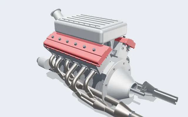
A V12 engine you can run, slice and take apart
Every crank, rod, cam and valve is a real solid, turning in your browser from one dial: the crank angle.
372 parts · 2,912 placements Turbogenerator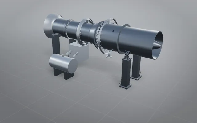
A gas turbogenerator in a container, every part mounted
A containerised power plant you can explode, isolate and section, light enough for any game engine.
173 parts · 1,022 placements Boom sprint core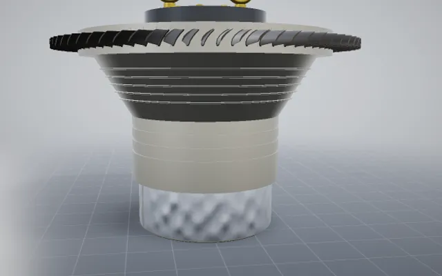
A supersonic engine core, rebuilt from public photos
Compressor, turbine, fuel system and build stand, stacked on the plate the way the shop builds it.
4,447 bodies in one build Rear differential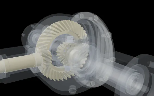
One wheel held, the other turns twice as fast
A complete rear differential with every bolt modelled, driven only by its mates, its feature tree open.
59 parts · 123 matesBuild your own part with NativeCAD
Try it free with the keyless evaluation · $200 per seat per year · Kernel SDK for products.